
Welding fixture for water tank

A technology for welding fixtures and water tanks, which is applied in the field of mechanical processing, can solve the problems of easily damaged cooling fins of the water tank, low welding efficiency, and increased labor intensity of workers, and achieve the effects of simple structure, improved work efficiency, and reduced labor intensity

Inactive Publication Date: 2013-12-25
SICHUAN HANGDA ELECTROMECHANICAL TECH DEV SERVICE CENT
View PDF0 Cites 0 Cited by
  • Summary
  • Abstract
  • Description
  • Claims
  • Application Information

AI Technical Summary

Problems solved by technology

In the past, when performing welding operations, it was necessary to remove the water tank after welding on one surface, then turn it over to the surface to be welded, press and fix it before welding, resulting in low welding efficiency, easy damage to the cooling fins of the water tank, and increased labor intensity

Method used


Image

  • Welding fixture for water tank

Examples


Embodiment Construction

[0009] The present invention will be further described below in conjunction with the accompanying drawings.

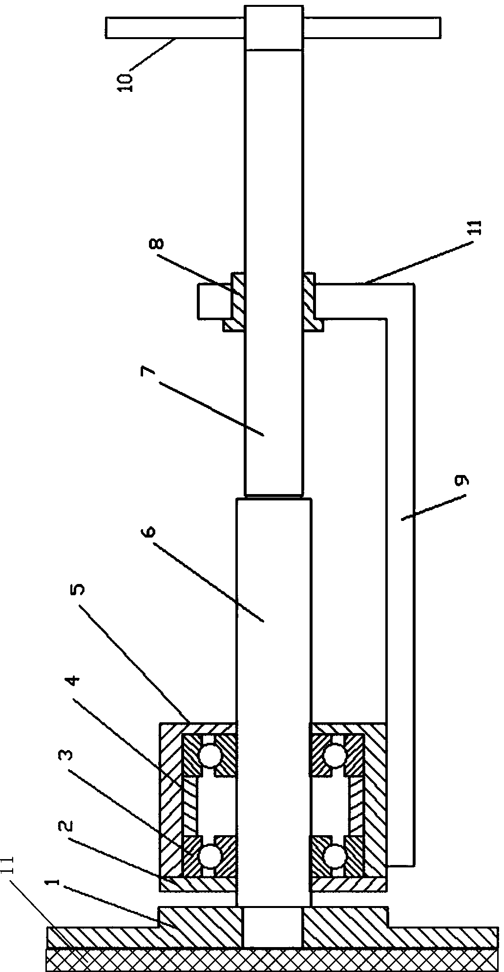
[0010] Such as figure 1 A water tank welding fixture shown includes a pressure plate 1, a bearing cover 2, a bearing 3, a bearing sleeve 5, a rotating shaft 6, a lead screw 7, a lead screw cover 8, a fixing plate 9, a hand wheel 10 and a lead screw support 11, The bearing 3 is installed in the bearing sleeve 5, the bearing cover 2 is installed on the opening end of the bearing sleeve 5, the bearing sleeve 5 is arranged on the fixing plate 9, and the rotating shaft 6 passes through the bearing sleeve 5, the bearing 3 and the bearing cover in sequence 2. A pressure plate 1 is fixedly installed on the left end of the rotating shaft 6, a screw support 11 is installed on the fixed plate 9, a screw cover 8 is arranged on the upper end of the screw support 11, and the screw 7 passes through the screw The sleeve 8 is on a horizontal line with the rotating shaft 6, and a handw...


PUM


Abstract

The invention discloses a welding fixture for a water tank. The welding fixture comprises a pressure plate, a bearing cover, a bearing, a bearing bush, a rotating shaft, a screw rod, a screw rod sleeve, a fixed plate, a hand wheel and a screw rod bracket, wherein the bearing is arranged in the bearing bush; the bearing cover is arranged at an open end of the bearing bush; the bearing bush is arranged on the fixed plate; the rotating shaft sequentially penetrates through the bearing bush, the bearing and the bearing cover; the pressure plate is fixedly arranged at the left end of the rotating shaft; the screw rod bracket is arranged on the fixed plate; the screw rod sleeve is arranged at the upper end of the screw rod bracket; the screw rod penetrates through the screw rod sleeve and is positioned on the same horizontal line with the rotating shaft; the hand wheel is arranged at one end of the screw rod; a sponge protecting layer (12) is arranged on the clamping surface of the pressure plate (1). The welding fixture is simple in structure and is convenient for use; greater pressing force can be provided during welding, and a workpiece to be welded can be turned in a pressing state; meanwhile, the damage to heat-radiating fins of the water tank is avoided.

Description

technical field [0001] The invention relates to the field of machining, in particular to a clamping device for welding. Background technique [0002] A water tank for a vehicle is a welded piece formed by tailor-welding of multiple parts. The weld seams are not only multi-faceted but also multi-directional, and need to be flipped and welded continuously. In the past, when performing welding operations, it was necessary to remove the water tank after welding on one surface, then turn it over to the surface to be welded, press and fix it before welding, resulting in low welding efficiency, easy damage to the cooling fins of the water tank, and increased labor intensity of workers. Contents of the invention [0003] The technical problem to be solved by the present invention is to provide a clamping device that has a simple structure, is easy to use, can provide a large pressing force during welding, and can turn over the workpiece to be welded in the pressed state. [0004...

Claims


Application Information

Patent Timeline
Patent Type & Authority Applications(China)
IPC IPC(8): B23K37/053
Inventor 林敏
Owner SICHUAN HANGDA ELECTROMECHANICAL TECH DEV SERVICE CENT
Learn More