
Pouring method of concrete pouring device for ultra-high steel pipe concrete column by conduit method

A technology for concrete filled steel tubular columns and concrete, which is applied in the processing of building materials, construction, building structure, etc., can solve problems such as discomfort, and achieve the effects of reducing pipe blockage, small expansion loss, and reliable pouring quality.

Inactive Publication Date: 2015-09-09
CHINA CONSTR SECOND ENG BUREAU LTD
View PDF5 Cites 2 Cited by
  • Summary
  • Abstract
  • Description
  • Claims
  • Application Information

AI Technical Summary

Problems solved by technology

[0008] The present invention provides a pouring method of super-high concrete-filled steel tube column concrete pouring device, which aims to solve the technical problem that the existing conduit pouring device and method are not suitable for pouring super-high concrete-filled steel tube columns with internal partitions

Method used


Image

  • Pouring method of concrete pouring device for ultra-high steel pipe concrete column by conduit method
  • Pouring method of concrete pouring device for ultra-high steel pipe concrete column by conduit method
  • Pouring method of concrete pouring device for ultra-high steel pipe concrete column by conduit method

Examples


Embodiment Construction

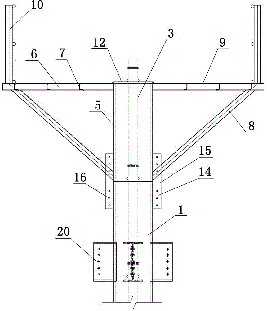
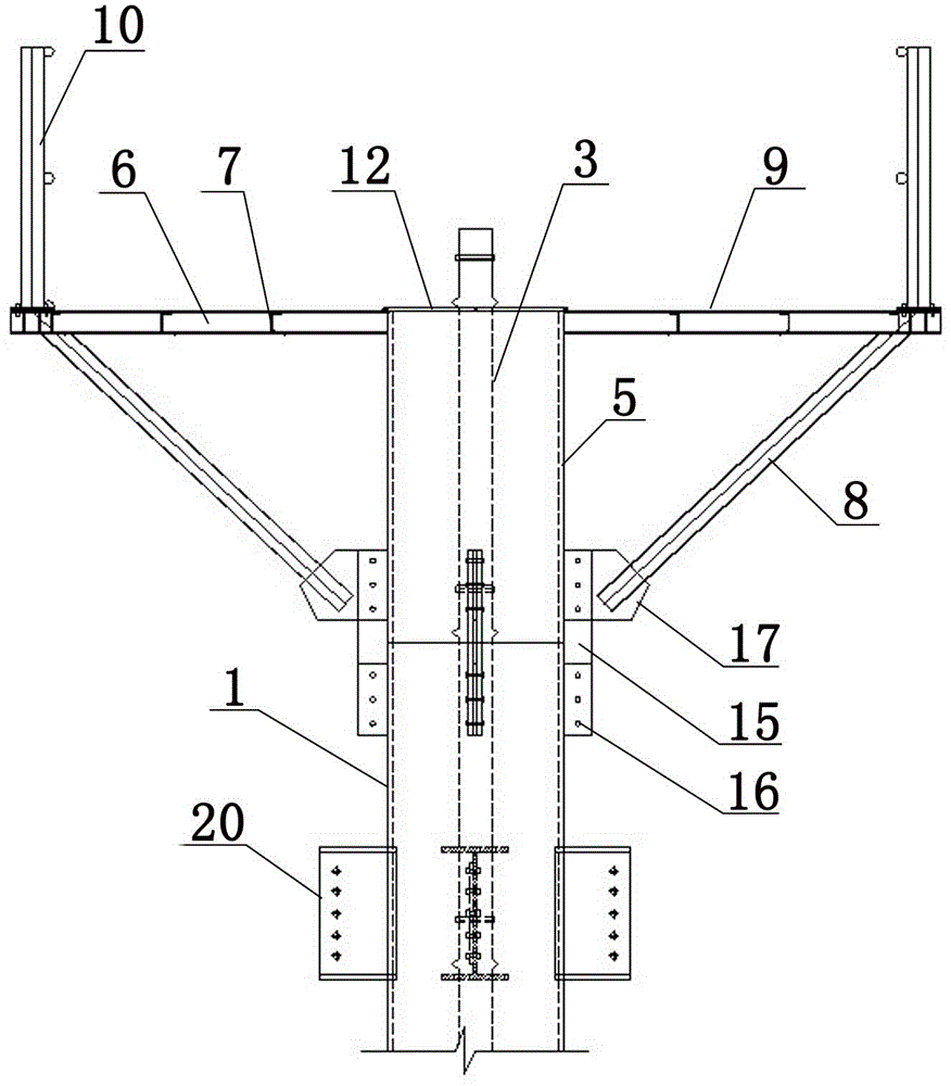
[0060] Examples see figure 1 As shown, in this ultra-high steel pipe concrete column concrete pouring device, the steel pipe 1 is provided with inner partitions 2 at intervals, the middle part of the inner partition 2 is provided with pouring holes 2.1, and air holes 2.2 are distributed around it. The device includes A movable platform on the top of the column connected to the top of the steel pipe 1, a conduit 3 inserted into the interior of the steel pipe, and a lower hopper 4 connected to the upper part of the conduit 3;

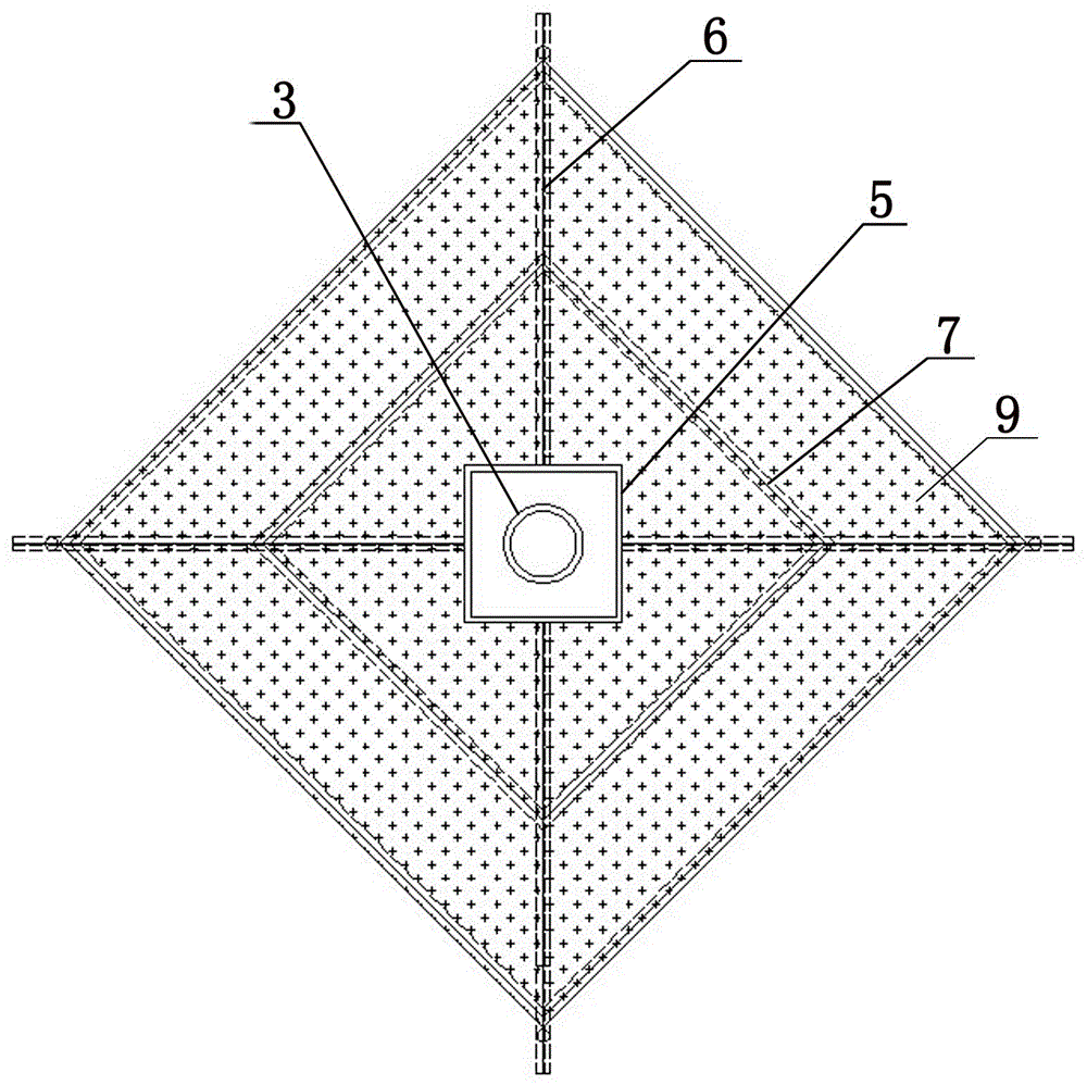
[0061] The column top movable platform is composed of joint steel pipe 5, main girder 6, secondary beam 7, diagonal brace 8, steel plate 9 and guardrail 10, and the nozzle at the top of joint steel pipe 5 is connected by hinge 11 with two clamps that can be flipped up. Plate 12, the middle of the two clamping plates 12 is provided with a conduit bayonet 12.1 for positioning the conduit, and there is also a ventilation hole 12.2 on the surface of the clamp...


PUM

PropertyMeasurementUnit
strengthaaaaaaaaaa
diameteraaaaaaaaaa

Abstract

The invention relates to a concrete pouring device and a concrete pouring method for an ultrahigh steel pipe concrete column tremie method. Inner baffles are arranged at intervals in a steel pipe. Pouring holes are formed in the middle parts of the inner baffles. Air vents are distributed on the peripheries of the inner baffles. The device comprises a column top movable platform which is connected onto the top of the steel pipe, a guide pipe which is inserted into the steel pipe, and a feeding hopper which is connected onto the upper part of the guide pipe. The column top movable platform consists of a joint steel pipe 5, a main beam, a secondary beam, diagonal bracings, a steel plate and a guardrail. Two clamping plates which can be upwards turned over are connected at the mouth of the top of the joint steel pipe through hinges. Guide pipe clamping mouths which are used for positioning the guide pipe are formed in the middles of the two clamping plates. The bottom of the joint steel pipe is fixedly connected with the steel pipe. The guide pipe is formed by sections in connecting way. The guide pipe is downwards inserted into the steel pipe through the joint steel pipe. The concrete pouring device and the concrete pouring method for the ultrahigh steel pipe concrete column tremie method have the advantages that the one-step pouring height can reach 29m, the requirement on the construction period and process can be met, the concrete column is detected as acceptable through ultrasonic detection, the pouring quality is reliable and the device and the method are particularly suitable for the pouring construction of ultrahigh steel pipe concrete with dense baffle holes.

Description

technical field [0001] The invention relates to a pouring method of a concrete pouring device for a steel pipe concrete column. Background technique [0002] Concrete filled steel tubes are widely used in high-rise buildings and long-span structures. At present, the pouring methods of steel pipe concrete include manual layer-by-layer pouring method, conduit pouring method, pumping jacking method and high-level drop without vibration method. However, the artificial layer-by-layer pouring method cannot be used for super-high concrete filled steel tubes with internal partitions. The construction preparation time of the pumping jacking method is long, and it is necessary to install flow-stop devices, short pipes, and also need to open feed ports and set pressure relief holes on the steel pipe column. The construction control procedures and construction devices are very complicated. In the case that there is an inner annular partition inside the steel pipe, the hole in the cent...

Claims


Application Information

Patent Timeline
Patent Type & Authority Patents(China)
IPC IPC(8): E04G21/02E04G3/24C04B28/04
Inventor 徐小洋张志明吕福磊白贺昶王伟季文涛
Owner CHINA CONSTR SECOND ENG BUREAU LTD
Learn More