Counterweight-discrete flywheel

A discrete, flywheel technology, applied in the field of flywheels, can solve the problems of variable inertia demand of flywheels, inability to meet equipment requirements, etc., and achieve the effect of reducing difficulty

Active Publication Date: 2013-12-25
HARBIN INST OF TECH
View PDF5 Cites 8 Cited by
  • Summary
  • Abstract
  • Description
  • Claims
  • Application Information

AI Technical Summary

Problems solved by technology

[0003]The purpose of the present invention is to solve the problem that the existing flywheel cannot meet the requirements of the equipment when its inertia requirements are variable, and to provide a discrete counterweight flywheel

Method used


Image

  • Counterweight-discrete flywheel
  • Counterweight-discrete flywheel

Examples


specific Embodiment approach 1

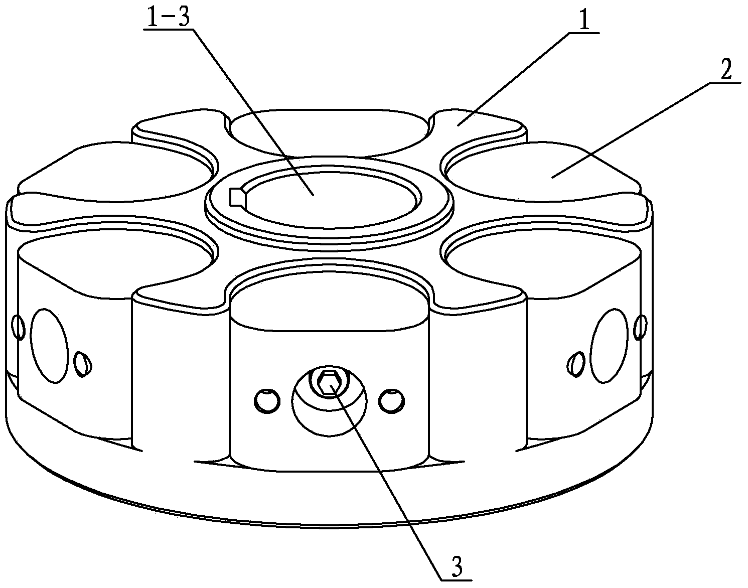
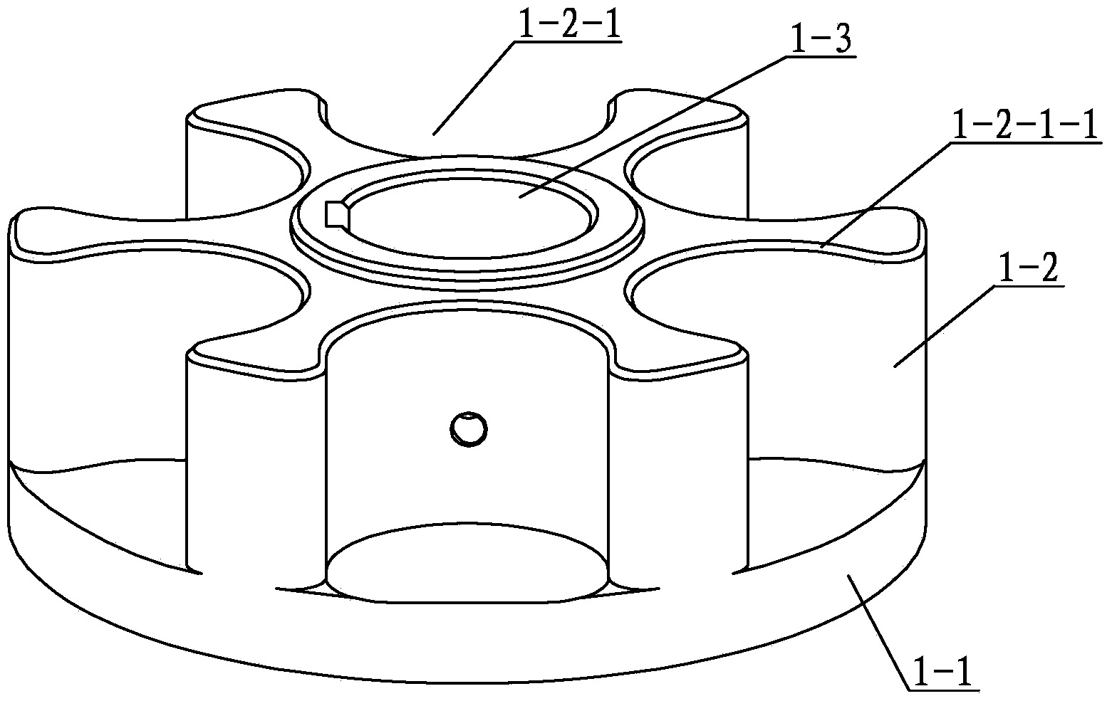
[0009] Specific implementation mode one: combine figure 1 and Fig. 3 illustrate this embodiment, the counterweight weight discrete flywheel of this embodiment includes a flywheel base 1 and several flywheel weights 2, and the flywheel base 1 is composed of a base 1-1 and a flywheel weight seat 1- 2, the base 1-1 is in the shape of a disk, the flywheel weight seat 1-2 is coaxially arranged up and down with the base 1-1, and the flywheel base 1 is provided with a central axis hole along the axis 1-3, the flywheel weight seat 1-2 is uniformly processed with four to eight semicircular grooves 1-2-1 along the periphery, and a flywheel weight is installed in each semicircular groove 1-2-1 Code 2, the flywheel weight 2 is connected with the flywheel base 1 through screws 3. When in use, pass one end of the engineering shaft through the center shaft hole 1-3 and fix it through the keyway.

specific Embodiment approach 2

[0010] Specific Embodiment 2: This embodiment is described with reference to FIG. 2 . The flywheel weight base 1-2 of this embodiment is integrated with the base 1-1. This design increases the stability of the flywheel base 1 . Other components and connections are the same as those in the first embodiment.

specific Embodiment approach 3

[0011] Specific Embodiment 3: This embodiment is described with reference to FIG. 2 . The number of semicircular grooves 1-2-1 in this embodiment is six. Design like this in order to ensure that the number of flywheel weights 2 is six. This number of flywheel weights 2 is the optimum value to meet the equipment requirements. Other compositions and connections are the same as those in Embodiment 1 or 2.


PUM


Abstract

The invention discloses a counterweight-discrete flywheel, which relates to a flywheel and is used for solving the problem that the equipment requirement cannot be met when the inertia demand of the flywheel is variable. The counterweight-discrete flywheel disclosed by the invention comprises a flywheel substrate and a plurality of flywheel counterweights, wherein the flywheel substrate consists of a base and a counterweight seat; the base is disk-shaped; the flywheel counterweight seat and the base are arranged coaxially one above the other; the flywheel substrate is provided with a central axle hole along the axle center; four to eight semicircular grooves are uniformly distributed along the periphery of the flywheel counterweight seat; a flywheel counterweight is arranged in each semicircular groove. The counterweight-discrete flywheel is mainly applied to equipment having higher momentary output power, and is used for storing energy at auxiliary time so as to play a role in lowering motor load.

Description

technical field [0001] The invention relates to a flywheel, in particular to a flywheel with discrete weights. Background technique [0002] A flywheel is an energy storage device that is widely used in machinery. In engineering and life, we often use some devices that require a large output power in an instant, and if the power is completely realized by the motor, it will cause a great burden on the electrical system. A typical example is a punch press in machining. However, the rotating flywheel is used to store energy during the auxiliary time, and then the kinetic energy of the flywheel is converted into the kinetic energy of the slider through the clutch device during the actual action time, which can reduce the burden on the motor. The existing flywheel is an integral disc structure. The energy stored in this structure is fixed. If the inertia requirement is variable, such as the flywheel assembly on the test bench, it is difficult to meet the flywheel with the integ...

Claims


Application Information

Patent Timeline
IPC IPC(8): F16F15/30
Inventor 朱延河刘刚峰赵杰
Owner HARBIN INST OF TECH
Why Eureka
Try Eureka