Glass plate width detection system based on machine vision

A machine vision and detection system technology, applied in instruments, measuring devices, optical devices, etc., to achieve high real-time and precision, high resolution, and high precision.

Active Publication Date: 2013-12-25
CHINA TRIUMPH INT ENG
View PDF5 Cites 25 Cited by
  • Summary
  • Abstract
  • Description
  • Claims
  • Application Information

AI Technical Summary

Problems solved by technology

[0003] The purpose of the present invention is to solve the technical problem that the cutting equipment cannot make correct actions according to the width of the glass plate, the position of the edge of the plate and the inf

Method used


Image

  • Glass plate width detection system based on machine vision
  • Glass plate width detection system based on machine vision
  • Glass plate width detection system based on machine vision

Examples


Embodiment 1

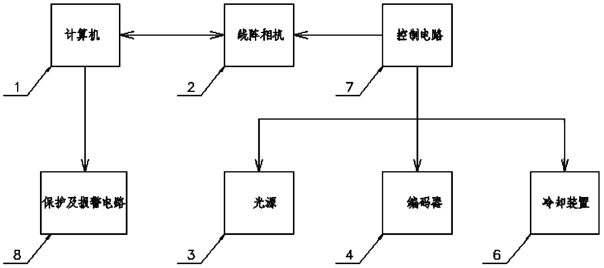
[0032] Such as figure 1 As shown, the computer drives the control circuit to control the cooling device, light source, and encoder. The cooling device is used to cool down the heating equipment such as the camera, the light source is used for graphic imaging, the encoder drives the camera to collect images, and then the computer reads the image information of the glass from the line array camera to process the image information.

Embodiment 2

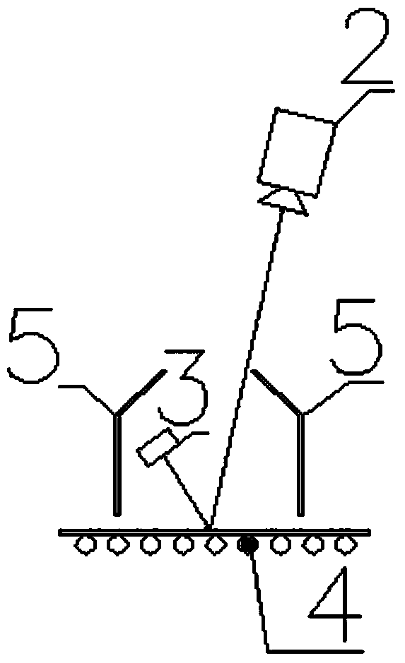
[0034] Such as figure 2 as shown, figure 2 The middle light source is a white LED strip light source. When there is glass below it, it will reflect and image on the glass surface. The line scan camera obtains the data of the glass plate by collecting the imaging area of ​​the light source. When no glass plate passes through or the glass plate has When it breaks, the image obtained by the line array camera is a full-scale low gray value image or an incomplete high gray value image; the encoder collects the roller speed pulse signal in real time, so that the line array camera can adjust the acquisition frequency in real time to ensure the authenticity of the image , will not stretch or compress, and can guarantee the accuracy of the measurement data. The line-scan camera is located at a certain height above the glass, and the light source and the line-scan camera are installed above the glass at a certain angle, so that the projection on the glass can be captured by the line-...

Embodiment 3

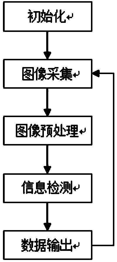
[0036] Such as image 3 As shown in , the computer program is initialized, and the line scan camera collects an image through the encoder signal. Perform image preprocessing such as smoothing and binarization on the image, and then detect the preprocessed image to obtain data such as the width of the glass in the image, the position of the edge of the sheet, the angle between the edge of the sheet and the direction of the glass, and the information of the broken sheet. And output the data information of the glass to the output device or send it to a third-party device, and then re-collect the image to start a new inspection.

[0037] The system has protection and alarm circuits to deal with some system failures, especially the failures that may cause damage to the equipment. The hood is used to block the ambient light and reduce the interference of the ambient light on the image.


PUM


Abstract

The invention relates to the technical field of glass production, in particular to a glass plate width detection system based on machine vision. The system comprises a line-scan digital camera, an encoder, a light source and a light-shielding cover, and is characterized in that the line-scan digital camera and the light source are located above a to-be-detected glass plate, the light source and the line-scan digital camera are not on the same vertical plane, the light-shielding cover is arranged on the outside of the light source, the line-scan digital camera is arranged on the outer side of the light-shielding cover, the two ends of the light-shielding cover are sealed, the upper portion of the light-shielding cover is provided with a hole, imaging of the light source on the to-be-detected glass plate can be seen in the hole through the line-scan digital camera, the to-be-detected glass plate is arranged on a roller bed, the roller bed is provided with the encoder, and the encoder collects the speed of the roller bed to control the speed of the line-scan digital camera in catching an image. Compared with the prior art, the system has the advantages that the image can be directly processed, information on the left side and the right side of the glass plate is information at the same moment, and consistency of data is achieved; the image processing speed is high, information of the glass plate is detected in real time, measured data are high in precision and high instantaneity and accuracy are achieved.

Description

[technical field] [0001] The invention relates to the technical field of glass production, in particular to a machine vision-based glass plate width detection system. [Background technique] [0002] In the glass production process, in order to reduce the damage to the cutting equipment caused by glass plate breakage and deviation, generally a glass plate width and broken plate information detection device is installed in front of the cold end cutting area, and the glass plate width, Information such as the position of the edge of the board and whether there is a break on the board surface (fried board), and send the above information to the wire control or cutting equipment through a specific communication method, so that the cutting equipment can make a decision in advance when the board edge deviates or there is a broken board. Self-protection action, thereby reducing damage to cutting equipment caused by deviation and broken boards. Various studies have shown that glass ...

Claims


Application Information

Patent Timeline
IPC IPC(8): G01B11/04
Inventor 刘路明彭寿王川申刘晓亮张荣松
Owner CHINA TRIUMPH INT ENG
Why Eureka
Try Eureka