
Loop traveling wave antenna generating radio frequency OAM on basis of metal ring cavity

一种行波天线、环形腔的技术,应用在环形天线、漏波导天线、天线等方向,能够解决OAM波束阶数限制、不利OAM波束复用等问题,达到加快实用化、实现复用的效果

Active Publication Date: 2013-12-25
ZHEJIANG UNIV
View PDF4 Cites 16 Cited by
  • Summary
  • Abstract
  • Description
  • Claims
  • Application Information

AI Technical Summary

Problems solved by technology

So far, most OAM beam generation methods come from the circular array antenna idea designed by Thide et al. in 2007, but the order of the OAM beam generated by this method is limited by the number of circular array antennas
Assuming that the number of circular array antennas is N, the order l of the OAM beams generated must be less than N / 2, and this method is not conducive to the multiplexing of OAM beams

Method used


Image

  • Loop traveling wave antenna generating radio frequency OAM on basis of metal ring cavity
  • Loop traveling wave antenna generating radio frequency OAM on basis of metal ring cavity
  • Loop traveling wave antenna generating radio frequency OAM on basis of metal ring cavity

Examples


Embodiment Construction

[0017] Below in conjunction with accompanying drawing, the present invention is described in further detail:

[0018] 1. Generation mechanism of radio frequency OAM beam based on ring traveling wave antenna

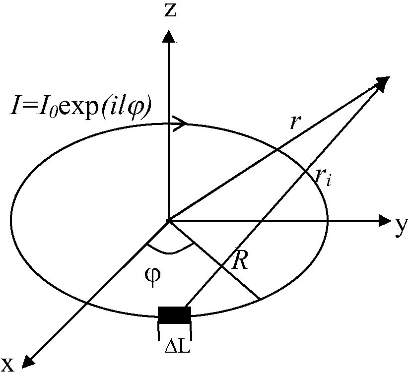
[0019] Any kind of antenna, whether it is an electric source antenna or a magnetic source antenna, as long as its spatial distribution is circular, the circle is symmetrical around the Z axis, the amplitude of the excitation source at each point on the ring is the same, and the phase is along the circumference of the ring. Continuously changing, satisfying distribution, where is the circular angle, l is an integer, which can be positive or negative, such as figure 1 As shown, this antenna is called a loop traveling wave antenna. Through electromagnetic numerical calculations, the radiation of this type of annular traveling wave antenna in space can produce a spiral phase The l-order OAM beam.

[0020] 2. Verification of radio frequency OAM beams generated by a rin...


PUM


Abstract

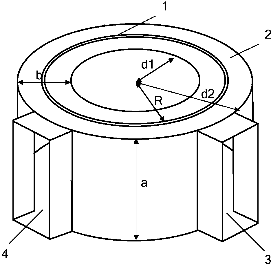
The invention discloses a loop traveling wave antenna generating radio frequency OAM on the basis of a metal ring cavity. The structure of an antenna body is the metal ring cavity, the top face of the metal ring cavity is provided with a seam along the circumference, two port metallic waveguides are formed in the positions, 1 / 4 away from the circumference, of the metal ring cavity to serve as double-source excitation ports of the antenna, and when microwave sources with the same frequency and a phase difference of + / - 90 degrees are input into the two double-source excitation ports, an electromagnetic field in the metal ring cavity is distributed as traveling waves around the circumference clockwise or anticlockwise. The seam in the top of the metal ring cavity forms a loop traveling wave antenna. The size of the metal ring cavity and the position of the seam are reasonably designed, so that switching of a microwave guide mode and an OAM mode can be achieved, and transmission of radio frequency OAM wave beams of different I orders is formed in a space. According to the loop traveling wave antenna, a traditional metal waveguide is used for achieving OAM wave beam transmission of a planar radio frequency waveguide structure, and the loop traveling wave antenna plays a very important role in developing radio frequency high-speed OAM communication.

Description

technical field [0001] The invention belongs to the technical field of OAM wireless communication, and relates to a ring traveling wave antenna for generating radio frequency OAM based on a metal ring cavity. Background technique [0002] As the world enters the mobile Internet era, the spectrum gap for mobile communication services is becoming increasingly serious. Due to the limited high-quality spectrum resources in the low frequency band, it is difficult to meet the new demands of mobile communications only by allocating new spectrum. In this case, it is particularly important to develop new technologies to improve the efficiency of the use of bits / Hz. At present, people have done a lot of research on expanding information capacity resources based on the dimensions of frequency spectrum, phase, and amplitude of electromagnetic waves, such as improving the spectrum utilization rate of a new intelligent wireless communication technology - cognitive radio; improving the sp...

Claims


Application Information

Patent Timeline
Patent Type & Authority Applications(China)
IPC IPC(8): H01Q7/00
CPCH01Q13/22
Inventor 郑史烈章献民池灏金晓峰
Owner ZHEJIANG UNIV
Learn More