
A kind of annular grounding device with impact resistance reduction function

A technology of impact resistance reduction and grounding device, which is applied in the direction of connecting contact materials, can solve problems such as difficulties, and achieve the effects of reducing impact grounding impedance, promoting spark effects, and enhancing local electric field strength

Active Publication Date: 2016-06-08
STATE GRID HUNAN ELECTRIC POWER +2
View PDF5 Cites 0 Cited by
  • Summary
  • Abstract
  • Description
  • Claims
  • Application Information

AI Technical Summary

Problems solved by technology

However, each of these methods has its own relative application conditions. It is still very difficult to design a grounding device that is technically and economically reasonable and meets the requirements of impact grounding impedance in areas with high soil resistivity.

Method used


Image

  • A kind of annular grounding device with impact resistance reduction function
  • A kind of annular grounding device with impact resistance reduction function
  • A kind of annular grounding device with impact resistance reduction function

Examples


Embodiment Construction

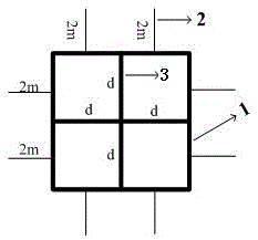
[0017] Such as figure 1 As shown, the annular grounding device of the present invention has a symmetrical structure, including a square grounding body 1 and two grounding electrodes 3 fixed in the square grounding body 1 and fixedly connected to the midpoint of the side of the square grounding body 1, two The grounding electrodes 3 are vertically intersected, and two grounding electrode outlet terminals 2 are fixed on each side of the square grounding body 1, and one end of the grounding electrode outlet terminal 2 is vertically intersected with the side of the square grounding body 1 , and the ground electrode outlet terminal 2 is on the same plane as the square ground body 1 .

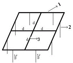
[0018] Such as figure 2 As shown, one end of the ground electrode outlet terminal 2 is vertically connected to the side of the square ground body 1, and the ground electrode outlet terminal 2 is perpendicular to the plane where the square ground body 1 is located.

[0019] figure 1 with figure ...


PUM

PropertyMeasurementUnit
Side lengthaaaaaaaaaa

Abstract

The invention discloses an annular grounding device with an impact impedance reducing function. The annular grounding device comprises a square grounding body and two grounding electrodes which are fixed in the square grounding body and fixedly connected with the side edges of the square grounding body. The two grounding electrodes intersect with each other in a perpendicular mode, and one or two grounding electrode outgoing line terminals are fixed to each of more than one side edge of the square grounding body. According to the annular grounding device, by additionally arranging the grounding electrode outgoing line terminals on the side edges of the square grounding body of the grounding device, the local electric field intensity of the annular grounding device is improved, the spark effect in the impact diffusion process is enhanced, and the purpose of reducing impact grounding impedance is achieved.

Description

technical field [0001] The invention relates to the technical field of lightning protection and grounding of transmission lines, in particular to a ring-shaped grounding device with the function of impact resistance reduction, which is suitable for the transformation of existing centralized grounding devices and new grounding devices for transmission line towers in areas with high soil resistivity such as mountainous areas. design. Background technique [0002] The impact grounding impedance of the centralized grounding device is an important parameter in the lightning protection design of the power system. When the transmission line is struck by lightning, the impact lightning current flows into the ground through the tower grounding device, and the impact grounding impedance has a direct impact on the lightning resistance performance of the transmission line under the action of a large impact current. In areas with high soil resistivity, due to the poor ability of the soi...

Claims


Application Information

Patent Timeline
IPC IPC(8): H01R4/66
Inventor 齐飞周卫华毛文奇周恒逸赵邈叶会生
Owner STATE GRID HUNAN ELECTRIC POWER
Learn More