
Self-breakdown gas switch and pulse power device

A gas switch and self-breakdown technology, which is applied in the direction of electrical components, spark gaps, and spark gap components, can solve the problems that affect the output pulse waveform stability, large voltage dispersion and randomness of pulse power devices, and achieve increased The effect of local electric field strength, improving stability, and promoting discharge conduction

Active Publication Date: 2022-03-25
北京京航计算通讯研究所
View PDF3 Cites 0 Cited by
  • Summary
  • Abstract
  • Description
  • Claims
  • Application Information

AI Technical Summary

Problems solved by technology

Since there is no external trigger intervention, the voltage between the two electrodes has large dispersion and randomness when the switch is turned on. In actual use, this dispersion and randomness will seriously affect the stability of the output pulse waveform of the pulse power device. sex

Method used


Image

  • Self-breakdown gas switch and pulse power device
  • Self-breakdown gas switch and pulse power device

Examples


Embodiment 1

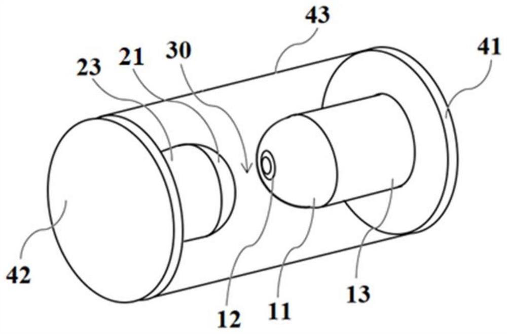
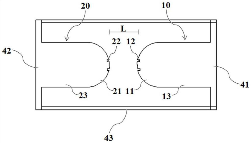
[0074] A self-breakdown gas switch includes a first electrode 10, a second electrode 20 and a casing, and the first electrode 10 and the second electrode 20 are arranged in the casing. The shell is a cylinder and includes a first bottom surface 41 , a second bottom surface 42 and a side wall 43 . The bottom diameters of the first bottom surface 41 and the second bottom surface 42 are 100 mm.

[0075] The first electrode 10 includes a first end portion 11 and a first cylinder 13 . The first end 11 is a hemisphere (1 / 2 sphere), one bottom surface of the first cylinder 13 is connected to the bottom surface of the hemisphere, and the other bottom surface is connected to the first bottom surface 41 of the casing. The diameter of the bottom surface of the hemisphere is equal to the diameter of the bottom surface of the first cylinder 13 , and the hemisphere and the first cylinder 13 have the same axis. An annular first groove 12 is formed on the top of the hemisphere at the first ...

Embodiment 2

[0081] The structure of the self-breakdown gas switch of this embodiment is the same as that of the self-breakdown gas switch of Embodiment 1, the only difference is that: no hemispherical first end 11 and second end 21, first groove 12, The second groove 22 is offered on the bottom surface of the first cylinder 13 and the second cylinder 23 respectively, and the distance between the bottom surface of the first cylinder 13 and the bottom surface of the second cylinder 23 provided with the groove is 10mm (that is, the gap 30 The length L is 10 mm). After testing, the breakdown jitter in this embodiment is about 5%.

Embodiment 3

[0083] The structure of the self-breakdown gas switch of this embodiment is the same as the self-breakdown gas switch of Embodiment 1, the only difference is that the outer diameter of the first groove 12 is 10 mm, and the outer diameter of the second groove 22 is 10 mm. After testing, the breakdown jitter in this embodiment is about 3%.


PUM

PropertyMeasurementUnit
lengthaaaaaaaaaa
diameteraaaaaaaaaa
diameteraaaaaaaaaa

Abstract

The invention relates to a self-breakdown gas switch and a pulse power device, the self-breakdown gas switch comprises a first electrode and a second electrode, the first electrode is provided with a first end part, and the first end part is provided with a first groove; the second electrode is provided with a second end part, and a second groove is formed in the second end part; wherein the first electrode and the second electrode are oppositely arranged, a gap is formed between the first electrode and the second electrode, and the gap is located between the first end part and the second end part. According to the self-breakdown gas switch capable of being used for the pulse power device, the grooves are formed in the end parts of the two electrodes, so that the non-uniform coefficient of an electric field between the two electrodes is increased, the electric field between the electrodes is non-uniformly distributed, the local electric field intensity is increased, the two electrodes are promoted to discharge and conduct, and the stability of voltage between the two electrodes when the switch is broken down is improved.

Description

technical field [0001] The invention relates to a self-breakdown gas switch, in particular to a field-enhanced high-voltage gas switch that can be used in a pulse power device. Background technique [0002] In pulse power devices, high-voltage self-breakdown gas switches are commonly used as discharge switches. The working voltage of this kind of switch is generally in hundreds of kilovolts to megavolts, and the breakdown time is generally in nanoseconds to microseconds. Due to the short pulse application time, it is difficult to synchronize the external trigger with the breakdown moment of the switch. Therefore, this type of switch is usually a self-breakdown switch. [0003] The structure of the self-breakdown switch is generally two metal electrodes facing each other, one of which is a high-voltage electrode and the other is a ground electrode. There is a gas gap between the two electrodes. When the pulse voltage gradually increases and reaches the gap breakdown voltage,...

Claims


Application Information

Patent Timeline
Patent Type & Authority Applications(China)
IPC IPC(8): H01T1/00H01T14/00
CPCH01T1/00H01T14/00
Inventor 寇科男贾文静戴弃君李昆高昕金晗冰刘冬闫玮琪刘军
Owner 北京京航计算通讯研究所
Learn More