Magnetic isolation squirrel cage outer rotor structure of a stator permanent magnet double rotor motor

A dual-rotor motor and outer rotor technology, applied in the direction of magnetic circuit shape/style/structure, magnetic circuit rotating parts, etc., can solve the problems of large loss, unable to fix and compress laminations, etc., and achieve the effect of reducing rotor loss

Inactive Publication Date: 2016-04-27
JIANGSU UNIV
View PDF3 Cites 0 Cited by
  • Summary
  • Abstract
  • Description
  • Claims
  • Application Information

AI Technical Summary

Problems solved by technology

[0004] In traditional motors, the rotor shaft that outputs torque is connected to the laminated rotor of the motor through a rotor bracket. The rotor bracket can not only transmit torque, but also fix and compress the laminations. In a dual-rotor motor, there is an inner rotor inside the outer rotor, and the cylindrical one The output of the torque of the outer rotor depends on the end face of the outer rotor, and because there is no space to install the rotor bracket and the shaft, the laminations cannot be fixed and compressed, so the outer rotor is mostly made of solid steel, resulting in greater loss;

Method used


Image

  • Magnetic isolation squirrel cage outer rotor structure of a stator permanent magnet double rotor motor
  • Magnetic isolation squirrel cage outer rotor structure of a stator permanent magnet double rotor motor
  • Magnetic isolation squirrel cage outer rotor structure of a stator permanent magnet double rotor motor

Examples


Embodiment Construction

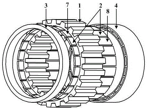
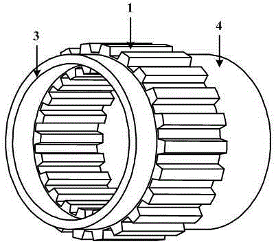
[0014] The outer rotor structure proposed by the present invention is as follows: figure 1 with figure 2 As shown, it is composed of an outer rotor body 1, a non-magnetic strip 2, a fixed end ring 3, and an output end ring 4.

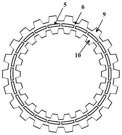
[0015] The outer rotor body 1 is laminated with silicon steel laminations 6, such as image 3 As shown, the inner and outer sides of the outer rotor body 1 are salient pole structures, and a group of closed groove groups 5 is arranged in the middle part of the yoke facing the outer salient pole 9 and the inner salient pole 10. The closed groove group 5 consists of a plurality of Composed of closed grooves with uniform direction. The axis of the closed groove group 5 is coaxial with the outer rotor body 1, the radial side walls of the closed groove group 5 are concentric arcs, the concentric arcs are coaxial with the outer rotor body 1, and the number of closed grooves is equal to that of the outer rotor body 1. The number of rotor poles on the rotor...


PUM


Abstract

The invention discloses a magnetic-isolation squirrel cage outer rotor structure of a stator permanent magnet double-rotor motor. The magnetic-isolation squirrel cage outer rotor structure of the stator permanent magnet double-rotor motor comprises an outer rotor body, non-magnetic-conduction strips, fixing end rings and output end rings, wherein the outer rotor body is an inner and outer side protruding pole structure formed by laminating silicon steel sheets, a plurality of sealed groves evenly distributed in the circumferential direction are distributed in the middle of a magnetic yoke right facing the outer side protruding pole and the inner side protruding pole of the outer rotor body, and one non-magnetic-conduction strip is embedded in one sealed groove. The two ends of each non-magnetic-conduction strip extend out of the outer rotor body, the shorter extending end of each non-magnetic-conduction strip is fixedly connected with the outer rotor body through one fixing end ring, and the longer extending end of each non-magnetic-conduction strip is fixedly connected with the outer rotor body through one output end ring. The magnetic-isolation squirrel cage outer rotor structure of the stator permanent magnet double-rotor motor can reduce loss of a rotor, the non-magnetic-conduction strips play a certain role in magnetic isolation, an inner motor and an outer motor can be independently controlled, and the output end rings provide an end surface for outputting the torque of the outer rotor.

Description

technical field [0001] The invention relates to a double-rotor motor, in particular to an outer rotor structure of the double-rotor motor, and belongs to the field of motor design. Background technique [0002] The structural feature of the double-rotor motor is that it has a stator and two inner and outer rotors. Most of the dual-rotor motors have permanent magnets on the outer rotors, which are difficult to fix and dissipate heat. For dual-rotor motors with a uniform magnetic field with permanent magnets on the outer rotor, the inner and outer magnetic fields are easy to affect each other, especially in weak During magnetic control. [0003] In the stator permanent magnet double rotor motor proposed in recent years, there is no permanent magnet and no winding on the outer rotor, which is a double salient pole structure. The magnetic field of the inner and outer motors is a non-uniform magnetic field type, and the magnetic field coupling of the inner and outer motors is mu...

Claims


Application Information

Patent Timeline
Patent Type & Authority Patents(China)
IPC IPC(8): H02K1/24
Inventor 莫丽红全力朱孝勇张涛李渊陈云云邱海兵
Owner JIANGSU UNIV
Why Eureka
Try Eureka