Circuit, method and displaying device for adjusting grid electrode opening voltage

A gate-on, voltage technology, applied in the direction of regulating electrical variables, output power conversion devices, control/regulation systems, etc., can solve problems such as large power loss

Active Publication Date: 2013-12-25
BOE TECH GRP CO LTD +1
View PDF7 Cites 7 Cited by
  • Summary
  • Abstract
  • Description
  • Claims
  • Application Information

AI Technical Summary

Problems solved by technology

[0004] To sum up, although the booster circuit in the prior art can meet ...

Method used


Image

  • Circuit, method and displaying device for adjusting grid electrode opening voltage
  • Circuit, method and displaying device for adjusting grid electrode opening voltage
  • Circuit, method and displaying device for adjusting grid electrode opening voltage

Examples


Embodiment 1

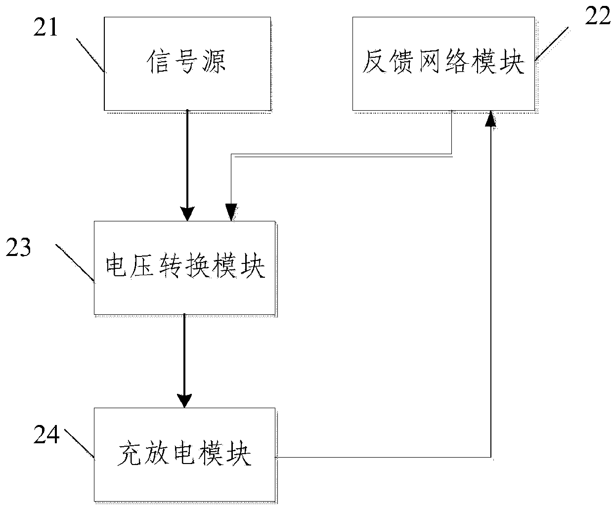
[0034] The embodiment of the present invention provides a circuit for adjusting the turn-on voltage of the gate. The schematic diagram of the circuit composition is as follows: figure 2 As shown, a signal source 21 , a feedback network module 22 , a voltage conversion module 23 and a charging and discharging module 24 .

[0035] The input voltage of the signal source 21 and the feedback voltage signal of the feedback network module 22 are input to the voltage conversion module, and the voltage conversion module 23 performs step-up conversion on the input voltage and the feedback voltage signal to obtain an output voltage, and the charging and discharging module 24 utilizes the output voltage and the power supply The voltage is charged and discharged, and the gate turn-on voltage is regulated.

[0036] The above-mentioned circuit for adjusting gate turn-on voltage takes the feedback voltage signal output by the feedback network module as input, and then uses the converted volt...

Embodiment 2

[0068] Embodiment 2 of the present invention also provides a method for adjusting the turn-on voltage of the gate, including: adjusting the ratio of the feedback resistors of the feedback network module to change the turn-on voltage of the gate.

[0069] By changing the ratio of the feedback resistors, the purpose of changing the gate open voltage can be finally achieved, but the whole process also involves the adjustment of the entire circuit, so after adjusting the ratio of the feedback resistors of the feedback network module: the voltage division of the resistors in the feedback network module is based on The ratio of the adjusted feedback resistance changes, the feedback network module compares the obtained divided voltage with the reference voltage, and outputs the feedback voltage signal; the feedback voltage signal and the clock signal output by the feedback network module are input to the buffer for boosting Convert to obtain the output voltage; control the MOS tube to...

Embodiment 3

[0078] Embodiment 3 of the present invention also provides a display device, which includes a display panel. The display panel includes a color filter substrate and an array substrate, and the array substrate has the circuit for adjusting the turn-on voltage of the gate provided in Embodiment 1 above. .

[0079] The display device may be any product or component with a display function, such as a liquid crystal display panel, electronic paper, OLED panel, mobile phone, tablet computer, television, monitor, notebook computer, digital photo frame, or navigator.


PUM


Abstract

The invention discloses a circuit for adjusting grid electrode opening voltage. The circuit for adjusting the grid electrode opening voltage comprises a signal source, a feedback network module, a voltage conversion module and a charging and discharging module, wherein input voltage of the signal source and feedback voltage signals of the feedback network module are input into the voltage conversion module, the voltage conversion module carries out voltage boosting conversion on the input voltage and the feedback voltage signals to obtain output voltage, and the charging and discharging module charges and discharges electricity through the output voltage and power source voltage and adjusts the grid electrode opening voltage. The invention further provides a method for adjusting the grid electrode opening voltage based on the circuit, and the grid electrode opening voltage is adjusted indirectly by adjusting the ratio of feedback resistance in a feedback network. The feedback voltage signals output by the feedback network serve as input, then converted voltage is used for periodic conduction of an MOS pipe, and further a pump capacitor is charged and discharged. The charging energy of a charge pump in a charge pump negative feedback system is equal to the energy consumed by loads, and unnecessary loss and consumption are reduced.

Description

technical field [0001] The invention relates to the field of display technology, in particular to a circuit, a method and a display device for adjusting gate turn-on voltage. Background technique [0002] Nowadays, liquid crystal displays have entered people's lives, and have become the protagonists of the entire display field due to their lightness, ultra-thinness, multi-color and high-definition characteristics. As the requirements for resolution and pixel quality are getting higher and higher, the power consumption of the entire voltage driving circuit is also increasing. [0003] The traditional gate turn-on voltage is to pre-design the required turn-on voltage, and then provide a suitable reference power supply when the circuit is implemented and provide the turn-on voltage to the gate through a voltage stabilizing circuit, so as to realize the turn-on of the gate and the writing of data, the circuit The schematic diagram of the principle is as figure 1 shown. At pre...

Claims


Application Information

Patent Timeline
IPC IPC(8): H02M3/155H02M1/08
Inventor 刘宝玉张亮许益祯孙志华
Owner BOE TECH GRP CO LTD
Why Eureka
Try Eureka