Manual stainless steel punching machine

A punching machine and stainless steel technology, applied in the field of manual stainless steel punching machines, can solve the problems of complex device structure, single function, poor practicability, etc., and achieve the effects of high safety performance, stable product quality and light machinery.

Inactive Publication Date: 2014-01-01
谢佰龙
View PDF9 Cites 2 Cited by
  • Summary
  • Abstract
  • Description
  • Claims
  • Application Information

AI Technical Summary

Problems solved by technology

[0002] At present, the disadvantages of stainless steel punching machines on the market are: complex structure, single function, poor practicability, and high cost

Method used


Image

  • Manual stainless steel punching machine
  • Manual stainless steel punching machine
  • Manual stainless steel punching machine

Examples


Embodiment Construction

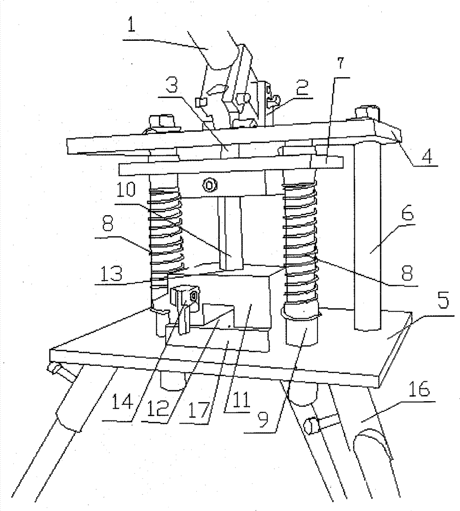
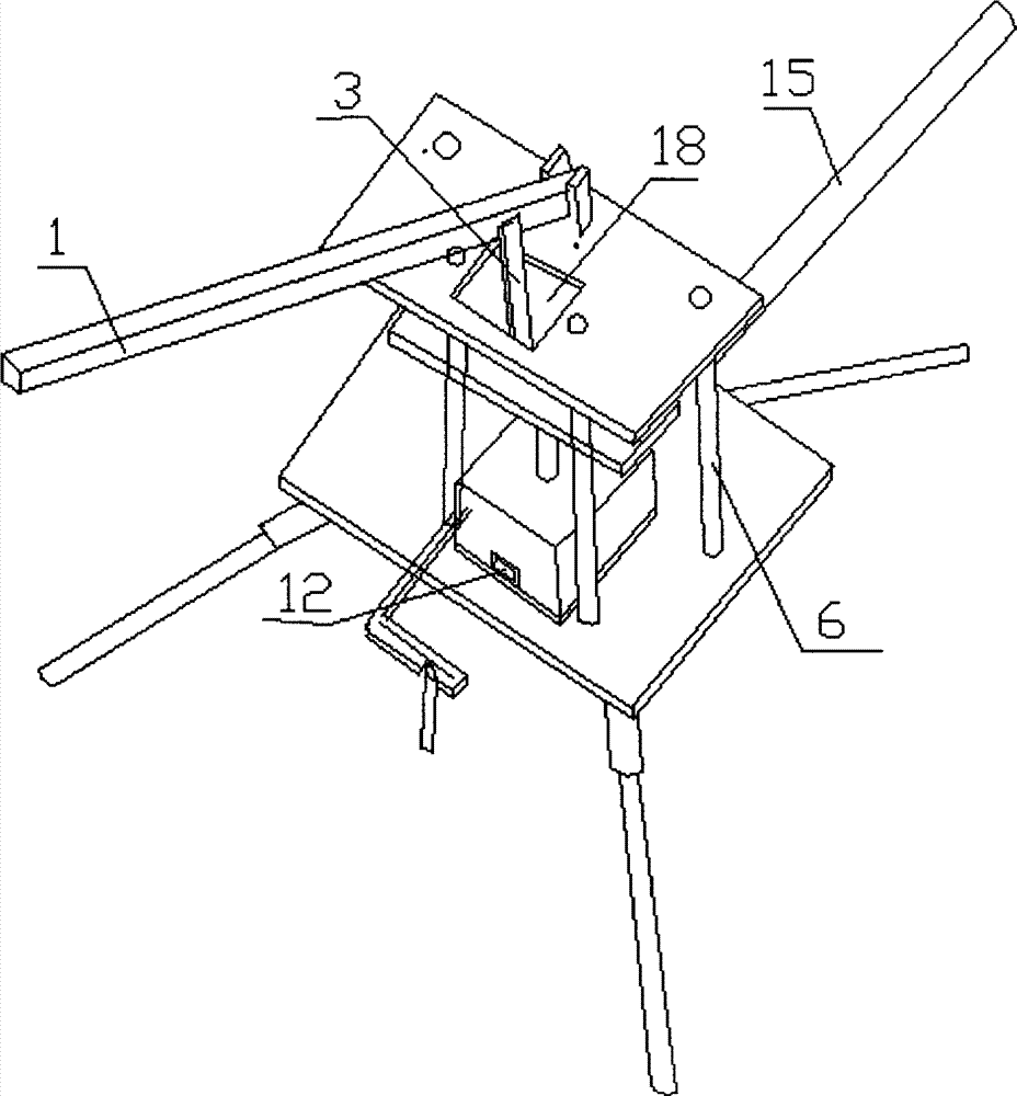
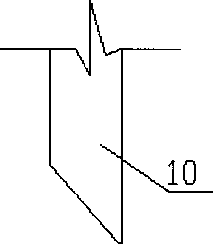
[0028] according to Figure 1-Figure 3 As shown, the present invention mainly includes: pressure rod 1, connecting seat 2, connector 3, upper machine plate 4, lower machine plate 5, fixed column 6, slide plate 7, spring 8, guide column 9, punch 10, mold body 11. Mold core 12, guide hole 13, positioning rod 14, mold core rod 15, bracket 16, lower template 17, access hole 18,

[0029] Manual stainless steel punching machine: the front end of the pressure rod 1 is movably connected with the connection seat 2 provided on the upper machine plate 4, and the lower parts of both sides of the upper machine plate 4 are symmetrically fixed and fixed with fixed columns 6, and the fixed columns 6 are fixedly connected with the lower machine plate 5 The front portion of the depression bar 1 is fixedly connected with the connector 3, and the connector 3 is fixedly connected with the slide plate 7 through the access hole 18 provided on the upper machine plate 4, and the slide plate 7 is provi...


PUM


Abstract

The invention discloses a manual stainless steel punching machine. the front end of a pressure lever is movably connected with a connecting base arranged on an upper machine plate, fixed columns are symmetrically and fixedly mounted on the lower parts of the two sides of the upper machine plate, and the fixed columns are fixedly connected with a lower machine plate; the front part of the pressure lever is fixedly connected with a connecting piece, the connecting piece is fixedly connected with a sliding plate through an access hole formed in the upper machine plate, the sliding plate is in movable and up-and-down connection with guide posts arranged on the two sides of the sliding plate through a plurality of springs; the sliding plate is fixedly connected with a punch, the punch moves up and down in a guide hole formed in a die body, and the guide hole is arranged corresponding to a track-shaped die core arranged in the die body; the front part of the die body is fixedly connected with a positioning rod, and the rear part of the die body is fixedly connected with a die core rod; the die body is fixedly connected with the lower machine plate through a lower die plate. The manual stainless steel punching machine has the advantages that the punching machine is high in efficiency, labor-saving, high in safety performance and is multifunctional; the punching machine is mechanical and portable, easy to operate and is safe; a moment arm structure adopts an inlaid copper bush, and the purposes of portability, labor-saving and durability are realized; a die and guide post structure is adopted, so that the accuracy of the punching machine is guaranteed.

Description

technical field [0001] The invention relates to a stainless steel processing device, in particular to a manual stainless steel punching machine. Background technique [0002] At present, the disadvantages of stainless steel punching machines on the market are: complex structure of the device, single function, poor practicability, and high cost. Contents of the invention [0003] The object of the present invention is to provide a manual stainless steel punching machine with simple structure, convenient and practical, and low cost. [0004] In order to solve the problems of the technologies described above, the technical solution of the present invention is: [0005] In this manual stainless steel punching machine, the front end of the pressure rod is movably connected with the connection seat provided on the upper machine board, and the lower parts of both sides of the upper machine board are symmetrically fixed with fixed columns, and the fixed columns are fixedly connec...

Claims


Application Information

Patent Timeline
IPC IPC(8): B21D28/24
Inventor 谢佰龙谢国海谢仟龙
Owner 谢佰龙
Why Eureka
Try Eureka