Supercharge Your Innovation With Domain-Expert AI Agents!

Method for machining roller cage

A processing method and cage technology, which are applied in the field of roller cages, can solve the problems of many process steps, difficulty in meeting the needs of reducing costs, and chips in processing.

Inactive Publication Date: 2014-01-01
NEEDLE ROLLER BEARING
View PDF6 Cites 4 Cited by
  • Summary
  • Abstract
  • Description
  • Claims
  • Application Information

AI Technical Summary

Problems solved by technology

[0004] see again figure 2 As shown, the existing roller cage 5 is to be made by using a ring body 8 as the raw material, and the roller cage 5 is formed by turning the mechanical processing method. However, in this processing method, it must remove quite a lot. Therefore, its material utilization rate is not good, which will cause waste of resources, and its machining accuracy is not easy to control through turning, and chips are generated during processing, which increases the time for subsequent processing, and its processing method not only reduces processing time Long, tool wear, and many process steps, resulting in high process costs, it is difficult to meet the demand for cost reduction

Method used


Image

  • Method for machining roller cage
  • Method for machining roller cage
  • Method for machining roller cage

Examples


Embodiment Construction

[0019] The detailed content and technical description of the present invention are now further described with examples, but it should be understood that these examples are for illustrative purposes only, and should not be construed as limitations on the implementation of the present invention.

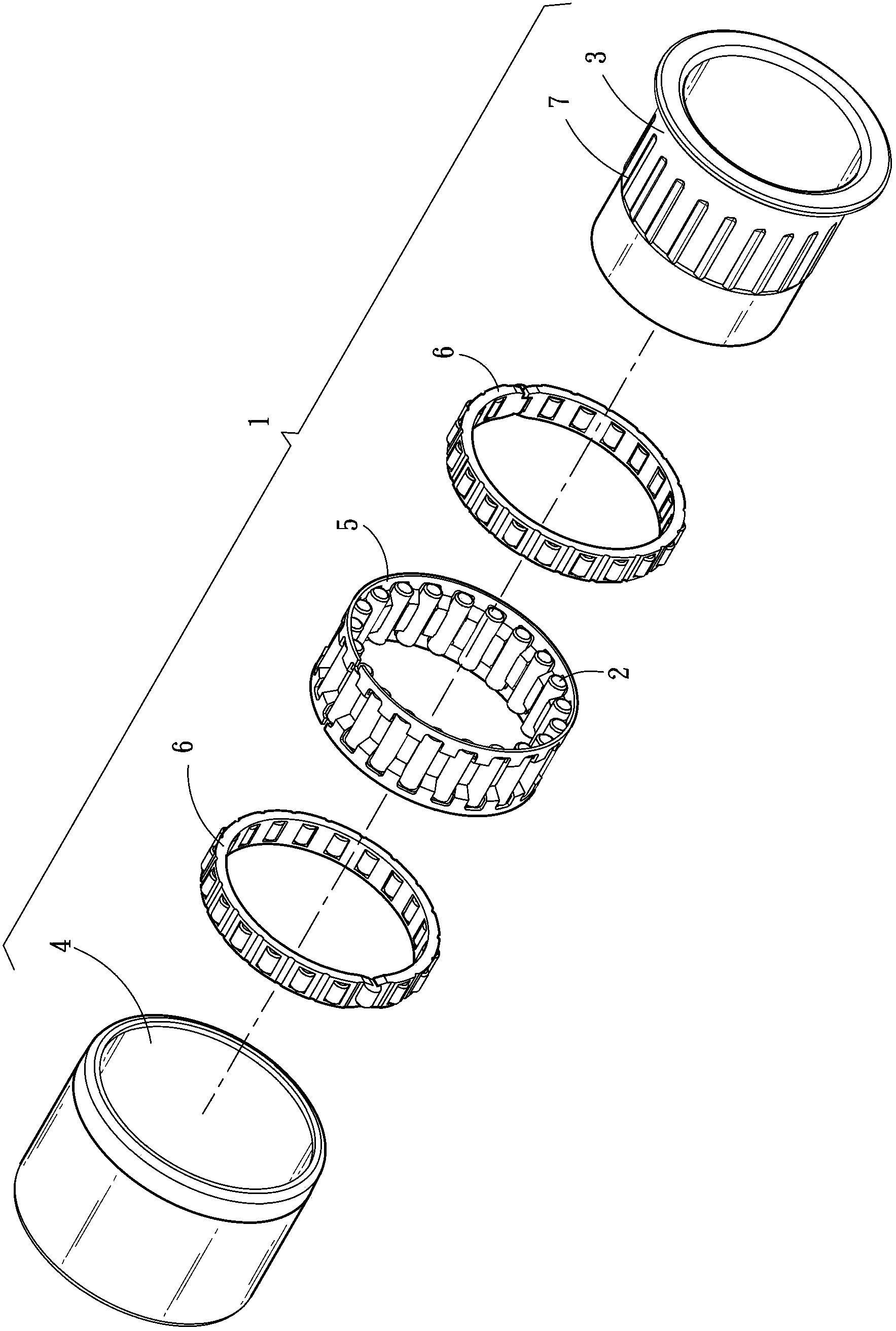
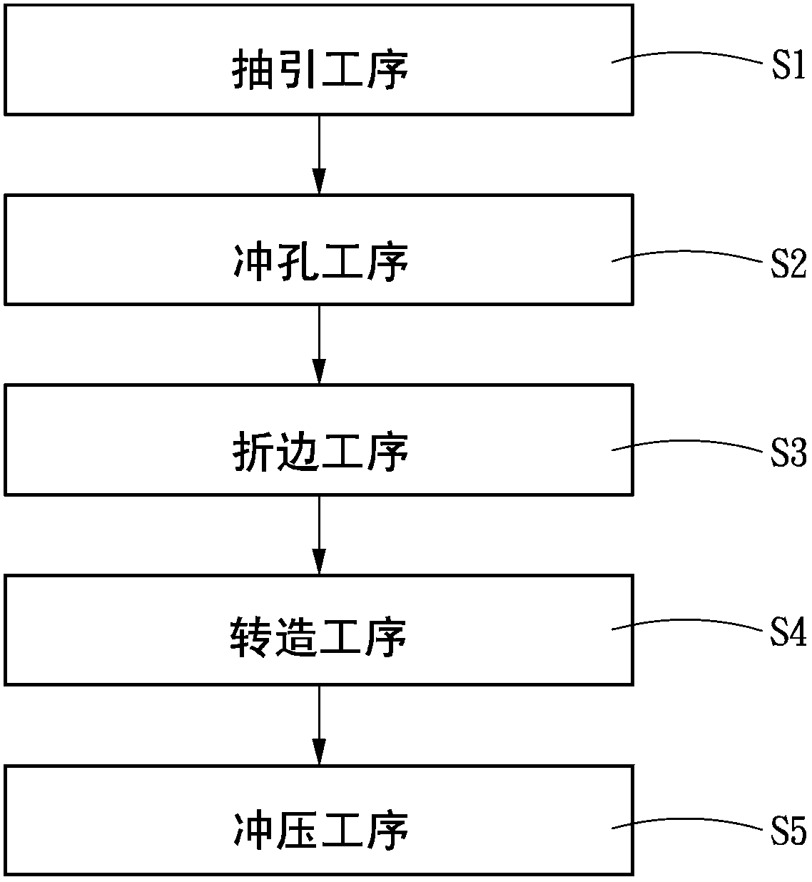
[0020] see image 3 , Figure 4 and Figure 5 As shown, the present invention is a roller cage processing method for forming a flat plate 10 into a roller cage 20. The steps include a drawing process S1, a punching process S2, and an edge folding process. S3, a transformation process S4 and a stamping process S5.

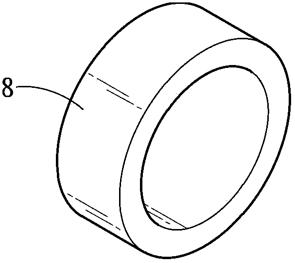
[0021] see again Figure 6 As shown, the extraction process S1 is to form the flat plate 10 into a sleeve 30 with a closed end 31 and an open end 32, and in order to increase the processing accuracy and avoid excessive deformation in a single forming, the extraction The drawing process S1 may include multiple drawing procedures, so as to gradually form the sleeve 30 thro...


PUM


Abstract

The invention provides a method for machining a roller cage, which is used for machining a flat plate into the roller cage. The method sequentially comprises the following steps of a drafting process, a perforating process, an edge folding process, a rolling process and a punching process, wherein the flat plate is subjected to the drafting process, the perforating process and the edge folding process to form a pipe sleeve, and the two ends of the flat plate respectively form a closed-end edge and an opening-end edge; after the pipe sleeve is subjected to the rolling process, and the inner surface and the outer surface of the pipe sleeve form an opposite convex-concave structure; finally the convex-concave structure is subjected to the punching process to form a plurality of through holes, thus the roller cage is formed. Therefore the method for machining the roller cage has high material utilization rate and low configuration cost and loss, and the requirements of reducing the manufacturing cost can be met.

Description

technical field [0001] The invention relates to a roller cage, in particular to a manufacturing method of the roller cage. Background technique [0002] see figure 1 As shown, it is an exploded view of the structure of the existing one-way clutch 1, which mainly includes a plurality of rollers 2, a first collar 3, a second collar 4 and a roller cage 5, wherein the first collar 3 and the second collar 4 are fitted and rotate relative to each other, and at least one roller bearing 6 can be arranged between the first collar 3 and the second collar 4, and the preferred number is one or two sets . In addition, the first collar 3 is sleeved inside the second collar 4, and the first collar 3 has a plurality of pockets 7 corresponding in number to the plurality of rollers 2, and the bottom surface of the plurality of pockets 7 is Inclined, and the distance between the deeper part and the second collar 4 is greater than the diameter of the roller 2 , and the distance between the s...

Claims


Application Information

Patent Timeline
Patent Type & Authority Applications(China)
IPC IPC(8): B21D35/00
Inventor 刘铭华
Owner NEEDLE ROLLER BEARING
Features
  • R&D
  • Intellectual Property
  • Life Sciences
  • Materials
  • Tech Scout
  • Unparalleled Data Quality
  • Higher Quality Content
  • 60% Fewer Hallucinations
Learn More