A lateral thruster and positioning method for machining aircraft thin-walled parts

A technology of thin-walled parts and lateral thrust, which is applied in the direction of metal processing machinery parts, positioning devices, metal processing equipment, etc., can solve the problems of small wall thickness processing of parts, affect CNC machining, and cannot compress parts, etc., to overcome extrusion Press-fit clamp deformation, good practicability, and the effect of improving reliability

Active Publication Date: 2015-11-18
SHENYANG AIRCRAFT CORP
View PDF7 Cites 0 Cited by
  • Summary
  • Abstract
  • Description
  • Claims
  • Application Information

AI Technical Summary

Problems solved by technology

[0002] It is an effective fast clamping method to tighten the parts through the lateral thruster. The lateral thrusters currently used generally can only load the thrust forward or forward and downward, and can only be used for tightening, not for positioning. , it is not suitable for thin-walled parts such as aircraft thin-walled parts, because when the inner shape of the part is removed and then CNC-machined to a thin-walled state, the thrust generated by the lateral thruster will deform the thin-walled part, resulting in the wall of the part Thick machining is small, and it will also loosen the thrust direction screws of the lateral thruster. The vibration during the CNC machining process will aggravate the loosening of the screws, which will eventually cause the lateral thruster to be unable to compress the parts and affect normal CNC machining.

Method used


Image

  • A lateral thruster and positioning method for machining aircraft thin-walled parts
  • A lateral thruster and positioning method for machining aircraft thin-walled parts
  • A lateral thruster and positioning method for machining aircraft thin-walled parts

Examples


Embodiment Construction

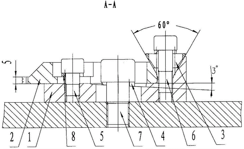
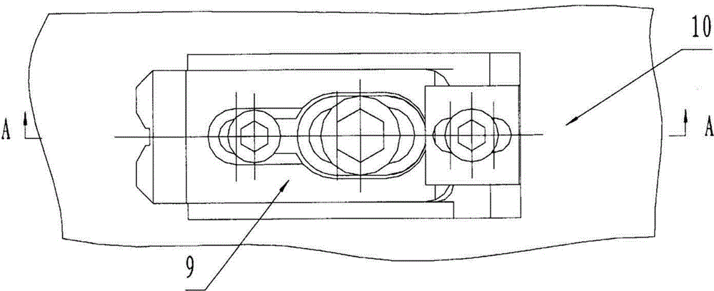
[0017] like Figure 1~2 Shown, a kind of lateral thruster that is used for the processing of aircraft thin-walled parts, described lateral thruster 9 comprises guide block 1, pressure plate 2 and fixture plate 10, and guide block 1 is positioned at the top of fixture plate 10, and guide block 1 There is a pressure plate 2 on the top, the end of the pressure plate 2 is zigzag, the screw I5 passes through the waist-shaped groove of the pressure plate 2 and is threadedly connected with the guide block 1, and the screw III7 passes through the waist-shaped groove of the pressure plate 2 and the guide block 1 and the fixture plate 10 Threaded connection, screw Ⅱ6 passes through the wedge 3 and is threaded with the pressure plate 2 and the guide block 1, the angle of the wedge 3 in the thrust direction is 60 degrees, the screw Ⅰ5 is close to the end, the screw Ⅱ6 is close to the end, and the screw Ⅲ7 Located in the middle of the above two screws, a spring washer 8 is provided between...


PUM


Abstract

A side thruster for aircraft thin-wall part processing comprises a guide block, a pressing plate and a clamp plate. The guide block is located above the clamp plate, the pressing plate is arranged above the guide block, the end of the pressing plate is of a zigzag shape, a first bolt passes through a waist-shaped groove of the pressing plate to be connected with the guide block in threaded manner, a third bolt passes through the waist-shaped grooves of the pressing plate and the guide block to be connected with the clamp plate in a threaded manner, a second bolt passes through a wedge block and the pressing plate to be connected with the guide block in a threaded manner, a spring washer is arranged between the first bolt and the waste-shaped groove of the pressing plate, and an angle gasket is arranged between the third bolt and the waste-shaped groove of the pressing plate. The positioning method includes: mounting an aircraft thin-wall part on the clamp plate, moving the side thruster to allow the zigzag-shaped surface of the end of the pressing plate to be in appearance contact with the aircraft thin-wall part, and respectively fixing the side thrusters on the appearance surface of the thin-wall part. By the side thruster, clamping reliability during numerical-control processing of the aircraft thin-wall part is improved, clamping deformation due to extrusion of the aircraft thin-wall part is avoided, risk of unqualified products is reduced, and practicability is good.

Description

technical field [0001] The invention relates to a fast clamping device and a positioning method for numerical control machining, in particular to a lateral thruster used for fast clamping and positioning of aircraft thin-walled parts and a positioning method for aircraft thin-walled parts. Background technique [0002] It is an effective fast clamping method to tighten the parts through the lateral thruster. The lateral thrusters currently used generally can only load the thrust forward or forward and downward, and can only be used for tightening, not for positioning. , it is not suitable for thin-walled parts such as aircraft thin-walled parts, because when the inner shape of the part is removed and then CNC-machined to a thin-walled state, the thrust generated by the lateral thruster will deform the thin-walled part, resulting in the wall of the part Thick machining is small, and it will also loosen the thrust direction screws of the lateral thruster. The vibration during ...

Claims


Application Information

Patent Timeline
Patent Type & Authority Patents(China)
IPC IPC(8): B23Q3/06
CPCB23Q3/06B25B11/00
Inventor 冯伟庆葛汝学王德生
Owner SHENYANG AIRCRAFT CORP
Why Eureka
Try Eureka