Plastic mold for electronic pen holder

A plastic mold and electronic pen technology, applied in the field of plastic molds, can solve problems such as complex structure, low production efficiency, and lower product qualification rate, and achieve the effects of simple device structure, improved work efficiency, and increased output

Inactive Publication Date: 2014-01-01
TAKAHATA PRECISION SUZHOU
View PDF4 Cites 2 Cited by
  • Summary
  • Abstract
  • Description
  • Claims
  • Application Information

AI Technical Summary

Problems solved by technology

[0002] When using the injection molding process to form plastic products, due to the structural factors of the mold, the injection mold for the pen holder of the electronic pen is generally complicated to form between the cavity structure and the gate, which makes the production efficiency low. The burr or the pen tube is not smooth enough, which will easily make the mold unqualified, reduce the qualified rate of the product, and increase the cost

Method used


Image

  • Plastic mold for electronic pen holder

Examples


Embodiment Construction

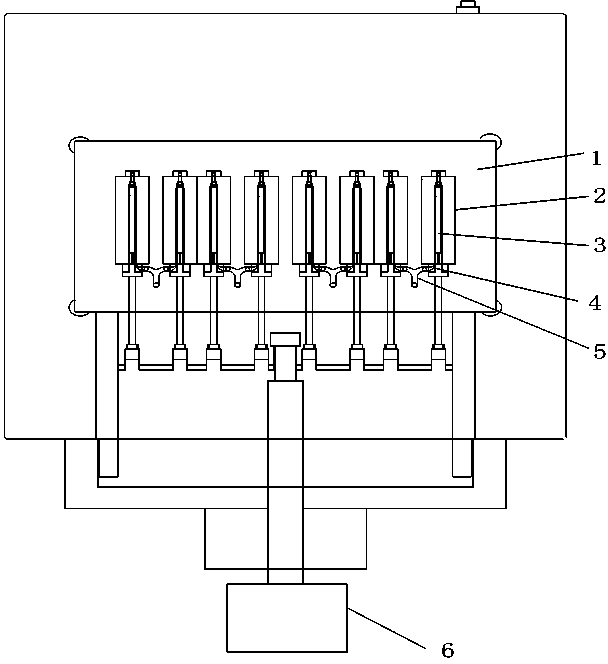
[0011] Such as figure 1 As shown, the plastic mold of the pen holder of the electronic pen includes a static template, a cavity plate 1 and a movable template. The cavity plate 1 is provided with a cavity 2, a gate 4 connected with the cavity 2, and a gate 4 communicated with the cavity plate 1. There are 8 cavity 2 on the cavity plate 1, the dimensions of the 8 cavities 2 are exactly the same, and the 8 cavities 2 are arranged in parallel in the horizontal direction, and every two cavities 2 are One unit, the two cavities of each unit are connected through 2 through the runner 5, and the runner 5 is connected with the corresponding gate; the shape of the cavity 2 is consistent with the shape of the penholder; one side of the cavity 2 is set There is a chute, and each chute is provided with a push rod 3, the push rod 3 is opposite to the cavity 2, and one end of each push rod 3 is fixed on the connecting rod, and the connecting rod is drivingly connected with the piston rod of...


PUM


Abstract

The invention provides a plastic mold for an electronic pen holder. The plastic mold comprises a static template, a cavity plate and a dynamic template, wherein eight cavities, sprues communicated with the cavities and runners communicated with the sprues are formed in the cavity plate, the overall dimensions of the eight cavities are completely consistent, the eight cavities are arranged in parallel along the horizontal direction, every two cavities are taken as a unit, the two cavities in each unit are communicated with each other through the runner, the runners are communicated with the corresponding sprues, the shape of the cavities is consistent with the shape of the pen holder, sliding chutes are formed in one sides of the cavities, push rods are arranged in the sliding chutes and are opposite to the cavities, and one ends of the push rods are fixed on connecting rods which are connected with piston rods of air cylinders by driving. Through the structure that one runner corresponds to two cavities for simultaneous injection molding, glue entering the cavities is ensured to be equal, and then the air cylinders are adopted for driving the push rods to complete molding. The plastic mold is simple in structure and fast in injection molding, and can increase the yield and effectively improve the working efficiency.

Description

technical field [0001] The invention relates to a plastic mold of an electronic pen holder. Background technique [0002] When using the injection molding process to form plastic products, due to the structural factors of the mold, the injection mold for the pen holder of the electronic pen is generally complicated to form between the cavity structure and the gate, which makes the production efficiency low. The burr or the pen tube is not smooth enough, which will easily make the mold unqualified, reduce the pass rate of the product, and increase the cost. Contents of the invention [0003] The purpose of the present invention is to overcome the deficiencies in the prior art and provide a plastic mold for the penholder of the electronic pen. [0004] The purpose of the present invention is achieved through the following technical solutions: [0005] The plastic mold of the pen holder of the electronic pen includes a static template, a cavity plate and a movable template....

Claims


Application Information

Patent Timeline
Patent Type & Authority Applications(China)
IPC IPC(8): B29C45/32B29C45/27
CPCB29C45/32B29C45/332
Inventor 冒建军冯志江
Owner TAKAHATA PRECISION SUZHOU
Why Eureka
Try Eureka