
Purifying equipment and purifying method for purifying catalytic cracking slurry oil

A technology of catalytic cracking oil slurry and purification equipment, which is applied in the petroleum industry, refining hydrocarbon oil, refining with the help of centrifugal force, etc., to achieve the effects of stable operation, increased separation stability, and improved efficiency

Active Publication Date: 2015-05-27
CHINA UNIV OF PETROLEUM (EAST CHINA)
View PDF5 Cites 0 Cited by
  • Summary
  • Abstract
  • Description
  • Claims
  • Application Information

AI Technical Summary

Problems solved by technology

[0006] The purpose of the present invention is to overcome the deficiencies of the existing single technology, use the sedimentation-centrifugal-electrostatic combined purification method to purify catalytic cracking oil slurry to improve the efficiency and utilization of oil slurry purification

Method used


Image

  • Purifying equipment and purifying method for purifying catalytic cracking slurry oil

Examples


Embodiment 1

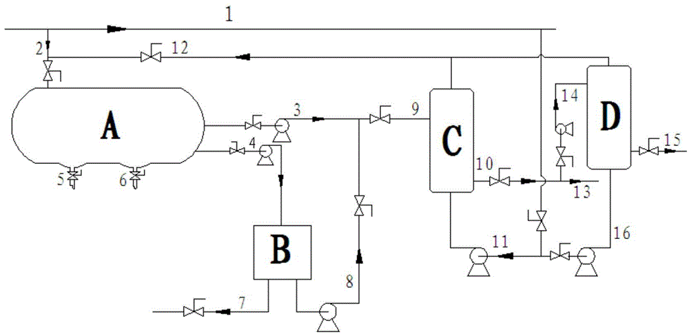
[0031]The heavy oil catalytic cracking oil slurry produced by a refinery contains 4.2g / L solid particles (GB / T511-2010). The oil slurry was settled in the settling tank for 12 hours at a settling temperature of 230°C. The content is 0.87g / L, the average solid content of the bottom flow of the settling tank is 9.1g / L, the bottom flow is sent to the centrifuge, the operating temperature of the centrifuge is 200°C, the centrifugal force of the continuous centrifuge is 6500G, and the semi-refined oil The solid content of the slurry is 0.92g / L. The oil slurry overflowed from the settling tank and centrifuged and semi-refined is sent to the first-stage electrostatic separator at the same time. The electrostatic voltage is 20kV, the temperature is 170°C, and the relative residence time is 10min (oil slurry The relative time of flowing through the separator filler), the solid content in the refined oil slurry after the first-stage electrostatic separation is 0.095g / L, and the desolidif...

Embodiment 2

[0042] The purified oil slurry of the primary electrostatic separator in Example 1 is directly sent to the secondary electrostatic separator. The electrostatic voltage of the secondary electrostatic separation is 35kV, the temperature is 160°C, and the relative residence time is 10min. After the secondary electrostatic separation The solid content in the refined oil slurry is further reduced to 0.008g / L, the total desolidification efficiency can reach 99.81%, and the recovery rate of the heavy oil slurry is still as high as 88%, which can meet the requirements of the solid content of raw materials for carbon fiber products.


PUM

PropertyMeasurementUnit
particle diameteraaaaaaaaaa

Abstract

The invention provides purifying equipment and a purifying method for purifying catalytic cracking slurry oil. According to the purifying method, the catalytic cracking slurry oil enters a settling tank from a pipeline (2), overflowing slurry oil is conveyed into a primary static separator from a pipeline (3), and a bottom flow is pumped into a centrifugal machine from a pipeline (4); a solid phase at the bottom of the settling tank is discharged from a discharge pipe at the bottom of the tank and sent into a lift pipe after centrifuged, and a liquid phase is pumped into the primary static separator from a pipeline (8) after centrifuged; a slurry oil product finishing static purification is sent into a product tank from a pipeline (10); and after fillers of the primary static separator is saturated through absorption, to-be-purified catalytic cracking slurry oil is introduced from a pipeline (11) and back back-washed from the bottom of the primary static separator, a backwash liquid returns to the settling tank from the top of the separator through a pipeline (12), and the purified slurry oil product is discharged into a product tank from a pipeline (15). The provided method is high in purification efficiency, stable in operation, long in production period, low in energy consumption and high in recycling rate of oil slurry, and effectively overcomes defects of a single separation method.

Description

technical field [0001] The invention belongs to the technical field of solid-liquid separation, and relates to a method for removing solid phase matter in catalytic cracking oil slurry, in particular to a purification device and a purification method for purifying catalytic cracking oil slurry. Background technique [0002] Catalytic cracking oil slurry is an important by-product of secondary processing catalytic cracking. At present, the annual output of catalytic cracking oil slurry in my country has exceeded 7.5Mt. The proportion of short-chain condensed ring aromatics in catalytic cracking oil slurry is relatively large, so it is expected to become an excellent raw material for the production of high value-added chemical products such as needle coke and carbon fiber. However, FCC oil slurry contains a certain amount of solid particles (>3g / L), mainly catalyst fine powder and a certain amount of coke powder, which seriously affects the utilization depth and range of oi...

Claims


Application Information

Patent Timeline
Patent Type & Authority Patents(China)
IPC IPC(8): C10G31/00C10G31/10
Inventor 郭爱军赵波张艳琦魏忠勋吉顺风陈坤沐宝泉王宗贤
Owner CHINA UNIV OF PETROLEUM (EAST CHINA)
Learn More