Edge forming device for loom

A loom and driving device technology, applied in the loom, selvage opening mechanism, textile and other directions, can solve the problems of damage to the driving device, the influence of the driving device becomes larger, and cannot cope with the high speed of the loom, so as to reduce the possibility of damage. Sex, the effect of reducing the load

Inactive Publication Date: 2016-08-10
TSUDAKOMA KOGYO KK
View PDF9 Cites 0 Cited by
  • Summary
  • Abstract
  • Description
  • Claims
  • Application Information

AI Technical Summary

Problems solved by technology

As a result, the influence of the inertia on the drive unit becomes greater, thereby increasing the load on the drive unit that drives the first swing unit, resulting in a greater possibility of damage to the drive unit that drives the first swing unit. Large, still unable to cope with the high speed of the loom

Method used


Image

  • Edge forming device for loom
  • Edge forming device for loom
  • Edge forming device for loom

Examples


Embodiment Construction

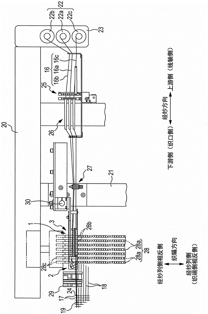
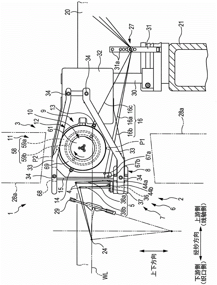
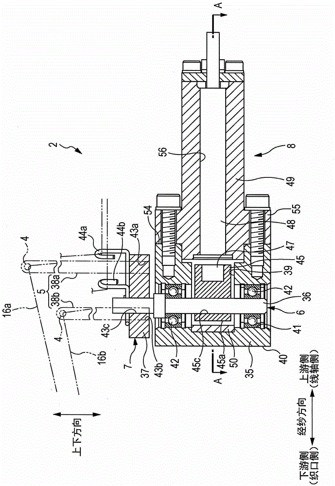
[0231] Below, based on Figure 1 to Figure 9 One embodiment of the edge forming device of the present invention will be described. In the following description, the direction parallel to the traveling direction of the warp yarn 18 is referred to as the "warp yarn direction", and in the warp yarn direction, the side where the warp yarn 18 is supplied to the unshown warp yarn bundle side, that is, the warp yarn delivery side is referred to as the "upstream side". , set the fabric fell side as "downstream side". In addition, the flying direction of the weft yarn 17 is referred to as the "weaving direction", and the weaving direction when the loom is viewed from the downstream side to the upstream side is also referred to as the "left-right direction".

[0232] figure 1 It is a partially enlarged plan view of a loom provided with the edge forming device 1 for the loom of the present invention. In addition, the side forming devices 1 are respectively provided at positions near t...


PUM


Abstract

The present invention provides an edge forming device of a loom, which is capable of increasing the speed of the loom. The edge forming device (1) forms a hemmed weave using the first edge yarns (16a, 16b) and the second edge yarns (16c), which includes means for displacing the path of the first edge yarns (16a, 16b) in the weaving direction. A side yarn path switching device (2) and a side yarn opening device (3) for displacing the path of the second side yarn (16c) in the up and down direction, the side yarn path switching device (2) has: a first side yarn (16a , 16b) the side yarn guiding member (5) of the pierced eyelet (4) and the drive device (8) for switching the position of the eyelet (4) between the left and right positions across the second side yarn (16c), the side yarn opening The device (3) includes a matching part (9) that displaces the path of the second side yarn (16c) in the up-down direction by cooperating with the second side yarn (16c) and displacing the second side yarn (16c). The two side yarns (16c) pass through the position on the side of the side yarn guide member (5) relative to the vertical direction relative to the eyelet (4) on the side of the first driving device (8) and through the front end of the side yarn guide member (5). Revolving on the revolving track at the position opposite to the first driving device (8).

Description

technical field [0001] The invention relates to an edge forming device of a loom for forming an edge weave from at least two edge yarns drawn out from a bobbin. Background technique [0002] Patent Document 1 discloses a device for winding and restraining a weft yarn with a plurality of side yarns at the weaving end of a fabric woven by a loom to form a side weave. [0003] In this device, a so-called lenge weave is formed from three edge yarns. The three side yarns are composed of two rotary yarns and one fixed yarn. When the two rotary yarns and one fixed yarn are inserted each time, their paths are reversed up and down to form openings. At the same time, the two rotary yarns are After a weft insertion, change the position on the left and right of the fixed yarn to constrain the weft yarn. [0004] In order to realize the motion of the side yarn, the device of Patent Document 1 has a first swing device that swings a cylindrical yarn guide needle that guides a fixed yarn ...

Claims


Application Information

Patent Timeline
Patent Type & Authority Patents(China)
IPC IPC(8): D03D47/40
CPCD03C7/04D03C7/06D03C11/00
Inventor 山村浩二
Owner TSUDAKOMA KOGYO KK
Why Eureka
Try Eureka