Cavitation eliminating device

A technology of cavitation and control devices, which is applied to parts of pumping devices for elastic fluids, non-variable pumps, machines/engines, etc., can solve problems such as low efficiency, reduced liquid output, and high cost, and achieve The effect of simple structure, reliable use and convenient operation

Inactive Publication Date: 2014-01-01
SHANDONG SHUANGLUN
View PDF4 Cites 7 Cited by
  • Summary
  • Abstract
  • Description
  • Claims
  • Application Information

AI Technical Summary

Problems solved by technology

[0005] In order to solve this cavitation phenomenon, at present, there are anti-corrosion blocks attached to the outer edge of the impeller to increase the corrosion resistance of the impeller, but this cannot solve the substantive problem of cavitation and reduce the sealing performance of the pump body. The backflow increases the inlet pressure. After the high-pressure liquid is introduced into the inlet, it is mixed with the inlet fluid. The disadvantage is that the liquid output of the pump is reduced and the efficiency is low. There are also double-suction impellers and inducer structures. The disadvantages are: Yes: complex structure and high cost
[0006] So far, there is no structure that can completely solve this cavitation phenomenon in the pump body.

Method used


Image

  • Cavitation eliminating device
  • Cavitation eliminating device
  • Cavitation eliminating device

Examples


Embodiment 1

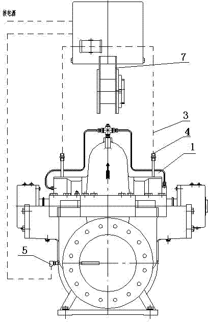
[0022] Embodiment 1: A kind of cavitation elimination device, comprises pump body 1 or tank body, is provided with cavitation elimination device on pump body 1 or tank body, and described cavitation elimination device comprises electric valve 2, intake pipe 3, probe tube 4. The flow probe 5 and the control device, the pump body 1 or the tank body is provided with a vent hole, the water inlet of the pump body 1 or the tank body is provided with a flow probe 5, and the probe tube 4 is inserted in the vent hole to detect The air outlet of the pipe 4 is connected with the cavitation area of ​​the pump body 1, and the air inlet is connected with the atmosphere through the air inlet pipe 3. The air inlet pipe 3 is provided with an electric valve 2, and the electric valve 2 and the flow probe 5 are respectively Connected with the control device, when the present invention is installed, the electric valve 2 can be fixed on the bracket 7, and the bracket 7 can be fixed on the pump body ...

Embodiment 2

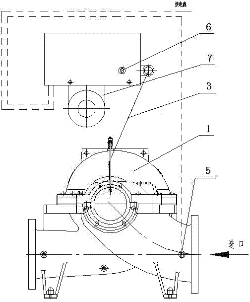
[0024] Embodiment 2: A kind of cavitation elimination device comprises a pump body 1 or a tank body. The pump body 1 is provided with a cavitation elimination device. The cavitation elimination device includes an electric valve 2, a regulating valve 6, an air intake pipe 3, a probe Pipe 4, flow probe 5 and control device, the pump body 1 or the tank body is provided with a vent hole, the water inlet of the pump body 1 is provided with a flow probe 5, the probe tube 4 is inserted in the vent hole, and the probe tube 4 The air outlet of the pump body 1 is connected to the cavitation area, and the air inlet is connected to the atmosphere through the air inlet pipe 3. The air inlet pipe 3 is provided with an electric valve 2, and the electric valve 2 and the flow probe 5 are connected with the control valve respectively. The device is connected, and the air inlet end of the air inlet pipe 3 is provided with a regulating valve 6, and the opening degree of the gas path of the air inl...


PUM


Abstract

The invention relates to the technical field of engineering machinery and particularly relates to a cavitation eliminating device. The cavitation eliminating device comprises a pump body. The cavitation eliminating device is characterized in that a cavitation eliminating device is arranged on the pump body and comprises an electric valve, a control device, an air inlet pipe, exploring tubes and a flow probe, wherein an air hole is formed in the pump body, the flow probe is arranged at a water inlet of the pump body, the exploring tubes are inserted into the air hole, air outlets of the exploring tubes are communicated with a cavitation region of the pump body, air inlets of the exploring tubes are communicated with the atmosphere through the air inlet pipe, the electric valve is arranged at the end of the air inlet pipe, and the flow probe and the electric valve are respectively connected with the control device. By utilizing the structure, the working efficiency of a water pump is not influenced, and long-term major damages caused by a cavitation phenomenon to the water pump are thoroughly solved; the cavitation eliminating device has the advantages of simple structure, convenience in operation, low cost, reliability in use and the like.

Description

technical field [0001] The invention relates to the technical field of engineering machinery, in particular to a cavitation elimination device. Background technique [0002] The so-called cavitation, also known as cavitation, is a special physical phenomenon of liquids. During the operation of the pump, due to some reasons, when the pressure in the local part of the pump drops to the saturated vapor pressure (vaporization pressure) of water at the corresponding temperature, the water starts to vaporize to generate a large number of bubbles, and the bubbles move forward with the water flow. , when it moves to a place with higher pressure, it will condense and collapse rapidly. The generation and collapse of bubbles in the water flow in the pump involves physical and chemical phenomena, and produces noise, vibration and erosion of the flow-through parts. This phenomenon is called cavitation of the pump. During the cavitation process of the water pump, due to the bubbles in...

Claims


Application Information

Patent Timeline
Patent Type & Authority Applications(China)
IPC IPC(8): F04D29/66
Inventor 刘元成薛增旭李春鲁
Owner SHANDONG SHUANGLUN
Why Eureka
Try Eureka