Mechanical seal device for nuclear power waste heat removal pump

A technology of mechanical sealing device and waste heat discharge pump, which is applied in the direction of engine sealing, mechanical equipment, engine components, etc., can solve the problem of high dimensional accuracy, poor mutual followability, and structural performance matching performance at the inlaid place. The overall performance of the fixed connection performance between the sleeve d and the shaft is not ideal, so as to achieve the effect of high sealing performance and high safety and reliability in use.

Active Publication Date: 2014-01-01
DANDONG COLOSSUS GROUP
View PDF5 Cites 9 Cited by
  • Summary
  • Abstract
  • Description
  • Claims
  • Application Information

AI Technical Summary

Problems solved by technology

The application of the above-mentioned prior art to the waste heat high-pressure hot water discharge pump in nuclear power plants cannot fully meet such requirements
Specifically, the structural performance of the moving ring assembly and the static ring assembly of the above-mentioned prior art, the matching performance of the moving ring and the static ring, the structural performance of the water seal device, the fixed connection performance of the shaft sleeve d and the shaft, and the combination of these Overall performance is not ideal
The followability of the moving ring and the static ring is not ideal. At the same time, both the moving ring and the static ring adopt a mosaic structure, and their mutual following is not good, which affects the sealing performance. The graphite moving ring and the ring seat are connected together by mosaic. The inlaying force of the ring seat on the moving ring causes deformation of the end face of the graphite moving ring, which affects the sealing performance, and the dimensional accuracy of the inlay is relatively high, which increases the difficulty of processing; The sleeve d is fixed to the transmission connection, and the screws are easy to loosen, resulting in seal failure; the water seal device cannot meet the absolute sealing performance requirements. Once the end faces of the mechanical seal of the moving ring and the static ring are crushed, the medium will produce a large amount of leakage through the water seal device e , can not guarantee the normal operation of the pump for a period of time, to provide sufficient time for emergency treatment

Method used


Image

  • Mechanical seal device for nuclear power waste heat removal pump
  • Mechanical seal device for nuclear power waste heat removal pump
  • Mechanical seal device for nuclear power waste heat removal pump

Examples


Embodiment Construction

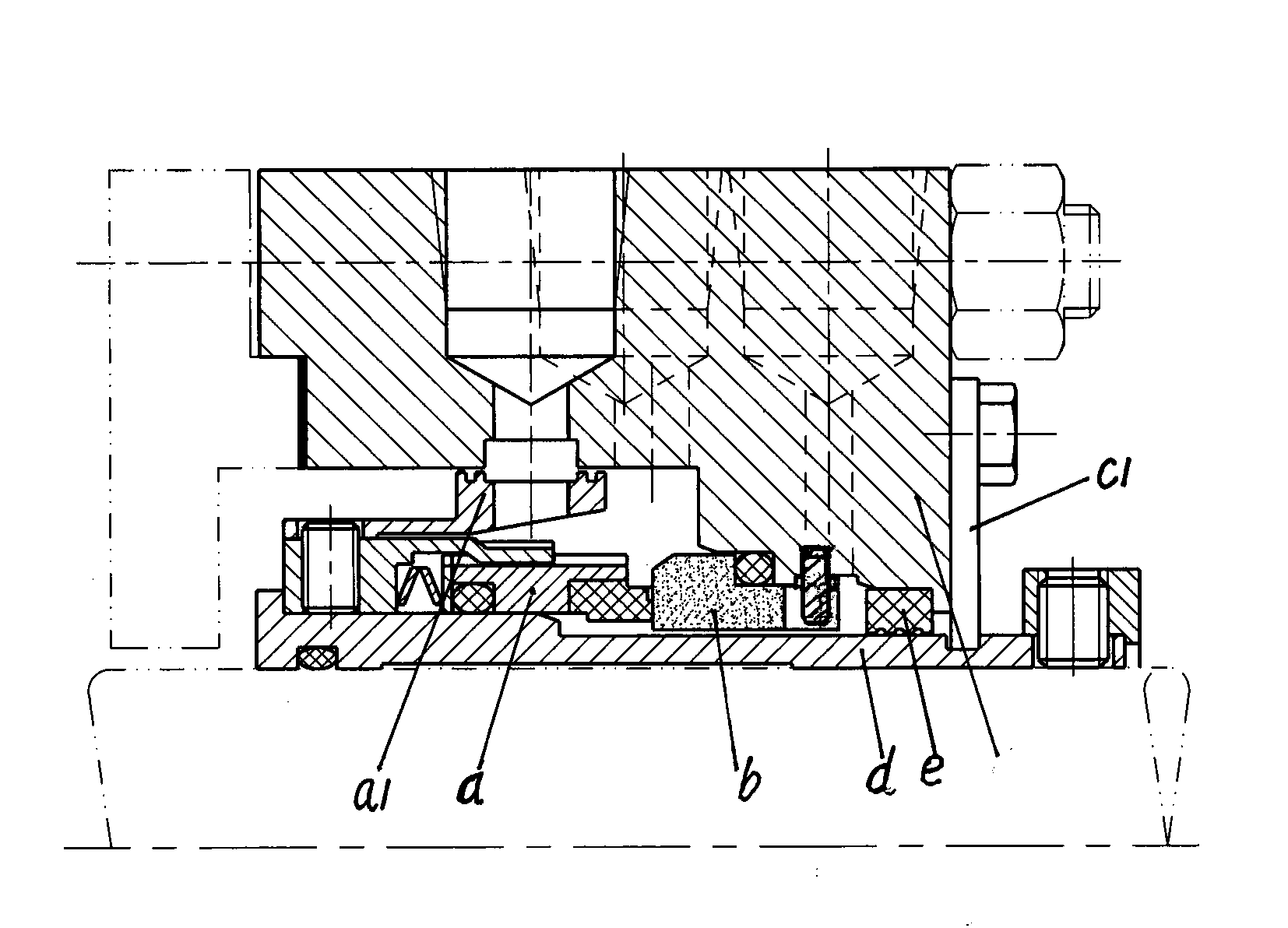
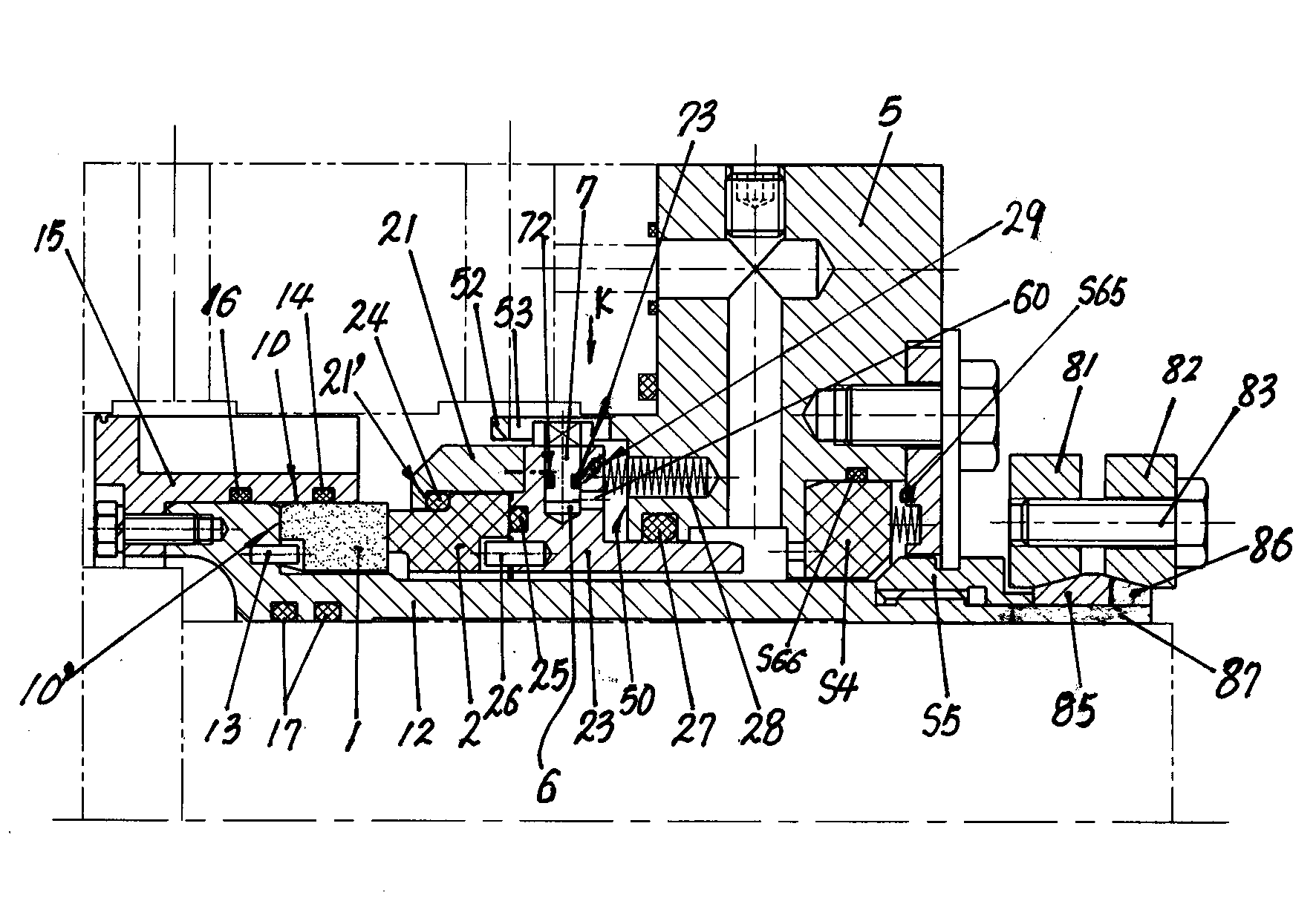
[0020] The invention comprises a moving ring assembly, a static ring assembly, a gland, and a water seal device on the gland, and is characterized in that the moving ring assembly consists of a moving ring 1, a shaft sleeve 12, a moving ring anti-rotation pin 13, and a moving ring auxiliary seal Ring 14, coolant pumping ring 15, pumping ring 15 sealing ring 16, shaft sleeve 12 sealing ring 17, the pumping ring 15 is fixedly connected with the rear end of the shaft sleeve 12 by bolts through the seam, and the pumping ring A sealing ring 16 is set between the inner ring surface of 15 and the mating surface of the outer ring of the shaft sleeve 12, and a notch seat 10 is provided on the shaft sleeve 12, and the moving ring 1 is installed in the notch seat 10 on the shaft sleeve 12. A moving ring auxiliary sealing ring 14 is arranged between the ring surface and the inner ring surface of the spigot seat 10; as shown in the embodiment of the drawings, the front end of the pumping ri...


PUM


Abstract

The invention relates to a mechanical seal device for a nuclear power waste heat removal pump. The mechanical seal device comprises a movable ring component, a static ring component, a gland, and a water seal device on the gland. A movable ring and a static ring which are mounted in a floating manner and matched with each other are stable, reliable, good in tracing ability and high in seal performance. The water seal device on the gland is of a two-conical-face matching type and has a seal function when the mechanical seal device of a pump shaft cannot seal to keep pressure in a pump cavity during accidents such as crushing and damaging of the seal device, massive media leaking out of the pump can be prevented, and high application safety and reliability are achieved.

Description

technical field [0001] The patent of the present invention relates to a mechanical seal device, especially a mechanical seal device used in a waste heat discharge pump of a nuclear power plant. Background technique [0002] According to the different working conditions of the mechanical seal device, the specific structure of the mechanical seal device is also different. [0003] The mechanical seal device used in the prior art for nuclear power plant waste heat high pressure hot water discharge pump is as attached figure 1 As shown, it includes a moving ring assembly a, a static ring assembly b, a gland c, and a shaft sleeve d. A water seal device e is installed on the gland c, and the moving ring assembly a is fitted on the shaft sleeve d. The ring assembly b is fitted on the gland c, and the cooling liquid pumping ring a1 is connected to the moving ring assembly a. The outer end of the shaft sleeve d is fixedly connected to the shaft through fastening screws. On the outer...

Claims


Application Information

Patent Timeline
Patent Type & Authority Applications(China)
IPC IPC(8): F16J15/16
Inventor 梅义宽纪德宏刘铁峰何德贵方明欣黄艳东腾朋
Owner DANDONG COLOSSUS GROUP
Why Eureka
Try Eureka