

LED bulb lamp easy for automatic assembly
An LED bulb lamp and automatic assembly technology, which is applied to the parts of lighting devices, cooling/heating devices of lighting devices, lighting devices, etc., can solve the problems of difficult automatic production, low production efficiency, and no interchangeability. , to achieve the effect of easy automatic assembly, small number of parts and beautiful appearance
- Summary
- Abstract
- Description
- Claims
- Application Information
AI Technical Summary
Problems solved by technology
Method used
Image

Examples
Embodiment 1
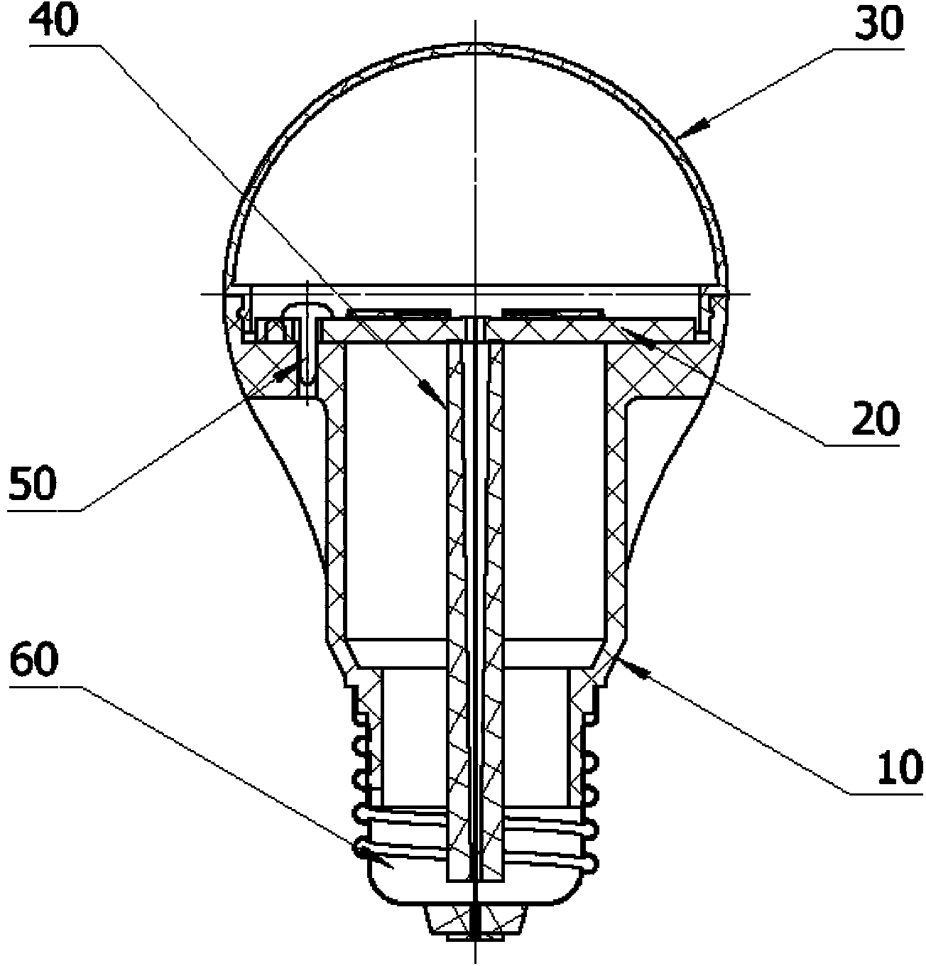
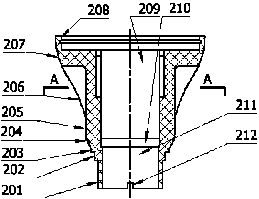
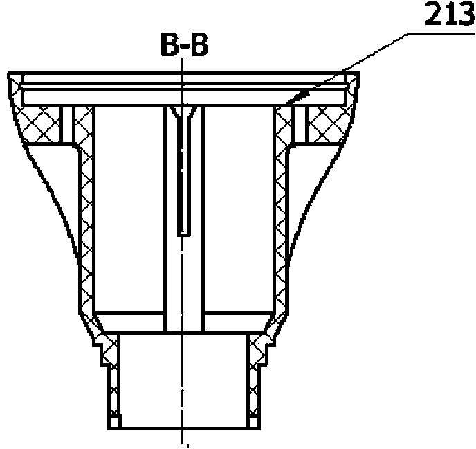
[0067] An LED bulb lamp that is easy to automatically assemble, including a lampshade 30, a lamp body 10, a fastener 50, a light source power supply assembly 20, a lead plate 40, and a lamp holder 60. In the groove, the upper end of the lamp body 10 is provided with an annular platform 213 formed by a depression, the light source power supply assembly 20 is installed on the annular platform 213, and the fastener 50 fastens the annular platform 213 and the light source power supply assembly 20 The inside of the lamp body 10 is provided with two symmetrical rectangular grooves 215 , the lead plate is inserted into the rectangular grooves 215 , and the lamp cap 60 is installed on the circular stepped tube 201 provided at the lower end of the lamp body 10 . When assembling LED bulb lamps, if an automatic assembly line is used, positioning pins should be used for the light source power assembly 20 to prevent movement due to inertia during displacement and affect the progress of the ...
Embodiment 2
[0075] Basically the same as Example 1, the difference is that, as Figure 2-5 As shown, the annular platform 213 is provided with three installation holes 217, which is different from the annular platform 213 with two installation holes 217 in that there is one more installation hole, and the rest are identical. The three mounting holes 217 are evenly distributed on the circle 218, one of which is set at the intersection of the circle 218 and the longitudinal centerline of the ring platform 213; On both sides of the circle 218, the angle between two adjacent mounting holes is 120°.
[0076] Figure 4-4 , Figure 4-5 It is a structural schematic diagram of the light source power assembly provided with 3 installation holes according to the present invention.
[0077] Such as Figure 4-4 , Figure 4-5 As shown: the light source power assembly includes a printed circuit board 403 and an LED chip 404 .
[0078] Such as Figure 4-6 As shown: the printed circuit board 403 is ...
Embodiment 3
[0080] Basically the same as Example 1, the difference is that, as Figure 2-6 As shown, the annular platform 213 is provided with four installation holes 217, which is different from the two installation holes 217 on the annular platform, there are two more installation holes, and the rest are exactly the same. The four mounting holes 217 are arranged at four intersection points of the circle 218 and the longitudinal and transverse centerlines of the annular platform 213, and the angle between two adjacent mounting holes is 90°. The four mounting holes provided on the annular platform 213 of the lamp body are in the same position and matched with the four mounting holes provided on the printed circuit board of the light source power supply assembly.
[0081] Figure 4-7 , Figure 4-8 It is a structural schematic diagram of the light source power assembly provided with 4 mounting holes according to the present invention.
[0082] Such as Figure 4-7 , Figure 4-8 As shown...
PUM
 Abstract
Description
Claims
Application Information