Measuring method for unknown aviation engine blade profile of CAD model

An aero-engine and surface measurement technology, applied in the direction of measuring devices, instruments, etc., can solve the problems of low accuracy, achieve good robustness, ensure measurement accuracy, and avoid the effects of measuring cross-sections and cross-section measurement points.

Inactive Publication Date: 2014-01-01
NORTHWESTERN POLYTECHNICAL UNIV
View PDF4 Cites 22 Cited by
  • Summary
  • Abstract
  • Description
  • Claims
  • Application Information

AI Technical Summary

Problems solved by technology

[0005] In order to overcome the shortcomings of the low accuracy of the existing three-coordinate measurement method for the profile of t

Method used


Image

  • Measuring method for unknown aviation engine blade profile of CAD model
  • Measuring method for unknown aviation engine blade profile of CAD model
  • Measuring method for unknown aviation engine blade profile of CAD model

Examples


Embodiment Construction

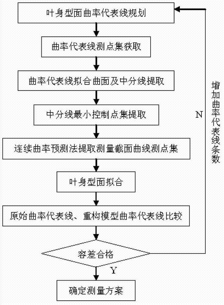
[0030] refer to Figure 1-6 . The present invention will be described in detail by taking the blade profile of a certain type of aero-engine compressor as an example.

[0031] Step 1: Analyze the structural characteristics of the blade, and plan five curves on the blade basin and the blade back surface along the main axis of the blade, and the curves are equally spaced on the blade back surface of the blade basin.

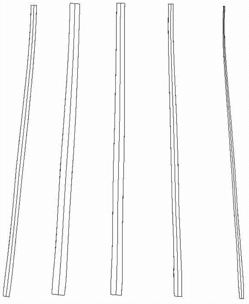
[0032] Step 2: Collect data points on the planned curve. According to the size of the blade in the main axis direction, use manual dots to collect 30 points on each section of the curve on the leaf pot and the back surface of the blade. The results are as follows: figure 2 shown.

[0033] Step 3: Import the above-mentioned curve measurement point set data into UG software and fit the curve, perform surface fitting on the corresponding curves on the surface of the leaf pot and leaf back, and extract the median line of the surface, the result is as follows image...


PUM


Abstract

The invention discloses a measuring method for an unknown aviation engine blade profile of a CAD model, wherein the measuring method is used for solving the technical problem that an existing aviation engine blade profile three-coordinate measuring method is low in precision. According to the technical scheme, multiple curves reflecting distribution states of curvature in the main shaft direction and located on the multiple blade profile are measured and analyzed, control points of the curves are figured out on the basis of curvature and allowance control, and then blade measuring sections are determined; on the basis of a curvature continuous prediction method, a measuring point set of each measuring section is planned, and three-coordinate measuring carried out on the unknown aviation engine blade profile of the CAD model is achieved. Because the blade measuring sections are selected according to blade profile curvature distribution characteristics, measuring point planning is carried out on the measuring sections on the basis of the continuous curvature prediction method, and the continuous curvature prediction method has better robustness, so extraction of molded line redundant points is reduced, meanwhile the situation that extraction points are fit with changes of measuring section molded line curvature is guaranteed, measuring efficiency is improved, and measuring precision can be guaranteed.

Description

technical field [0001] The invention relates to a three-coordinate measurement method of an aeroengine blade profile, in particular to an aeroengine blade profile measurement method with an unknown CAD model. Background technique [0002] In the field of aero-engines, blades are the core components of turbomachinery, and the aerodynamic shape of the blades will directly affect the performance of aero-engines. In order to improve the thrust-to-weight ratio of the engine, the profile of the blade is usually designed as a twisted variable-section curve, and accurate blade profile data is the key and prerequisite for the realization of CAD / CAM, digital reverse manufacturing, product inspection and quality control of the blade. In order to obtain the data of the blade profile, it is necessary to measure the blade profile. The measurement of the blade profile can be generally planned into two modes. The first mode is called the detection error mode. In this mode, the measured surf...

Claims


Application Information

Patent Timeline
IPC IPC(8): G01B21/20
Inventor 汪文虎赵德中崔康靳洪超裴景东王姝成浪永王渊彬解晓娜张艳
Owner NORTHWESTERN POLYTECHNICAL UNIV
Why Eureka
Try Eureka