Mounting and locking mechanism of automatic vending machine sealing door

A technology for vending machines and sealing doors, which is applied to coin-free or similar appliances, coin-operated equipment for distributing discrete items, and coin-operated equipment for distributing discrete items, etc. Good, the electromagnetic lock is cumbersome to install and maintain, hot air or cold air is easy to leak, etc., to achieve the effect of simple structure, low production and installation costs, and long service life

Active Publication Date: 2014-01-01
TIANJIN LEIYUNFENG TECH
View PDF5 Cites 6 Cited by
  • Summary
  • Abstract
  • Description
  • Claims
  • Application Information

AI Technical Summary

Problems solved by technology

[0003] In the above structure, there are problems in the structure, installation method and locking structure of the existing valve, specifically: 1. The thermal insulation effect of the valve structure is not good, and the hot or cold air in the vending machine is easy to leak; 2. The valve passes through A long through shaft is hinged at the front of the warehouse, not only inconvenient to disassemble, but also the long through shaft will damage the internal structure of the valve; 3. The existing valves usually use electromagnetic locks. When the user takes out the goods, the valve will automatically go up. Swing down, when approaching the electromagnetic lock, the electromagnetic lock will absorb the valve, thereby closing the warehouse. When the vending machine has no power, the electromagnetic lock will lose its function, causing all the valves to be opened at will, resulting in the loss of goods Or damaged, and the installation and maintenance of the electromagnetic lock is also cumbersome

Method used


Image

  • Mounting and locking mechanism of automatic vending machine sealing door
  • Mounting and locking mechanism of automatic vending machine sealing door
  • Mounting and locking mechanism of automatic vending machine sealing door

Examples


Embodiment Construction

[0036] Below in conjunction with the examples, the present invention is further described, the following examples are illustrative, not limiting, and the protection scope of the present invention cannot be limited by the following examples.

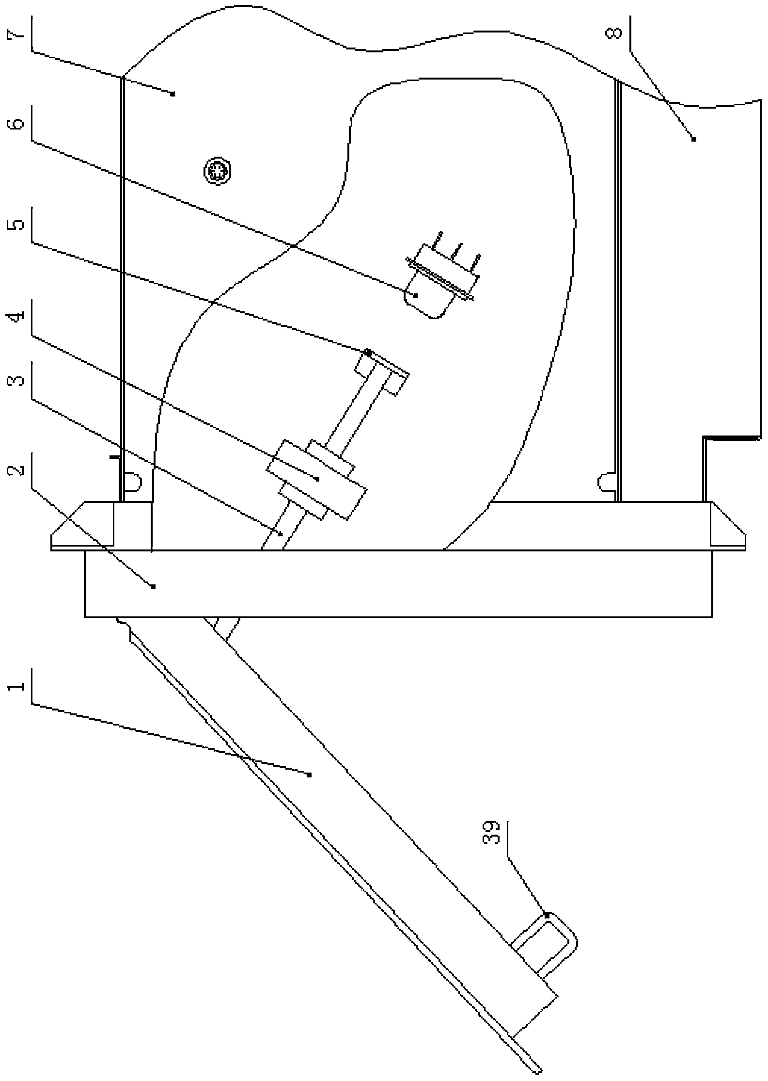
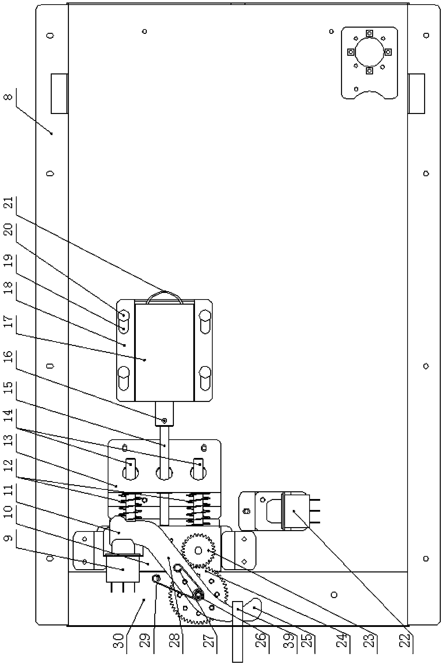
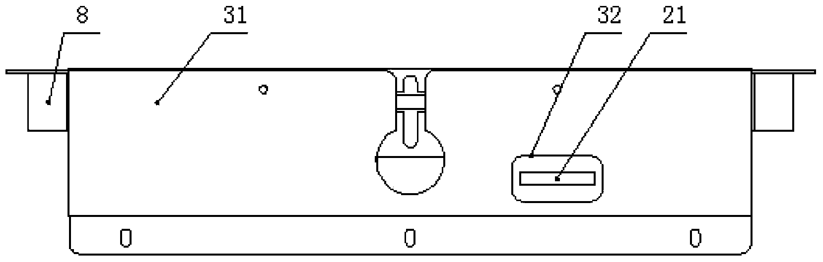
[0037] A vending machine hermetic door locking mechanism, such as Figure 1~6 As shown, including valve 1, warehouse 7 and control module, a plurality of warehouses are embedded in a matrix shape on the front face of vending machine 40, and 2 hinged valves are installed at the front end of each warehouse. The innovation of the present invention lies in: all A short strip-shaped opening 38 in the vertical direction is arranged at the lower end of the front end of the warehouse, and a hook 39 is installed on the valve opposite to the opening. The rotating and tightening locking device is closely connected, and the said swinging and tightening locking device can make the valve close to the front end of the warehouse, and a trigger link 3 is ...


PUM


Abstract

The invention relates to a mounting and locking mechanism of an automatic vending machine sealing door. An open hole is formed at the lower end of the front end face of each goods bin, a hook is mounted on the inner side of a valve opposite to each open hole in position, and enters the corresponding open hole to be closely connected with a swinging, rotating, tensioning and closing device mounted at the bottom of the corresponding goods bin, each swinging, rotating, tensioning and closing device can enable the corresponding valve to be closely connected on the front end face of the corresponding goods bin in an abutted manner, a trigging connecting rod is mounted on the inner side of each valve, and a switch is mounted in the side wall, opposite to the corresponding triggering connection rod in position, of each goods bin, and connected with a control module. The valves and the goods bins are matched with each other, and the valves have excellent heat insulating performance, so that hot air or cold air in the goods bins is enabled to be less prone to leaking, and safe storage of articles in the goods bins is guaranteed; a connecting structure between each valve and the corresponding goods bin is simple and convenient to operate, simple in structure and low in manufacturing and mounting cost; the valves and the goods bins are in close fit, so that further heat insulation effect is realized, and the integral structure is enabled to be more safe.

Description

technical field [0001] The invention belongs to the technical field of a sealed door structure and installation and locking of an automatic vending machine, in particular to an installation and locking mechanism of a sealed door of an automatic vending machine. Background technique [0002] The vending machine can automatically identify the coins input by the user, automatically calculate the change, and automatically transport the goods to the pick-up port according to the goods selected by the user. It can hold a variety of goods, such as beverages, cigarettes, lunch boxes, fruits or vegetables, etc. , the user can operate by himself, and the whole transaction is very convenient. In a vending machine, the structure of the model used to sell fruits or vegetables is: including a housing, a valve, and a warehouse, and a plurality of warehouses are inserted in the housing in a matrix-arranged shape, and each warehouse is at the front end. It is also possible to hinge the valv...

Claims


Application Information

Patent Timeline
Patent Type & Authority Applications(China)
IPC IPC(8): G07F11/00
Inventor 张保强魏韧李德政
Owner TIANJIN LEIYUNFENG TECH
Why Eureka
Try Eureka