Method of manufacturing magnetic element and magnetic element

A technology of magnetic components and manufacturing methods, applied in the direction of inductance/transformer/magnet manufacturing, coil manufacturing, electrical components, etc., can solve the problems of complicated closed magnetic circuit assembly, defective or damaged magnetic cores, etc.

Active Publication Date: 2014-01-01
SUMIDA CORP
View PDF5 Cites 3 Cited by
  • Summary
  • Abstract
  • Description
  • Claims
  • Application Information

AI Technical Summary

Problems solved by technology

[0002] In a magnetic element having a core made of a sintered ferrite core and a coil (winding part) on which a wire is wound around the core, there is a defect or breakage in the core and a closed magnetic circuit is formed. Complicated assembly, etc.

Method used


Image

  • Method of manufacturing magnetic element and magnetic element
  • Method of manufacturing magnetic element and magnetic element
  • Method of manufacturing magnetic element and magnetic element

Examples


Embodiment Construction

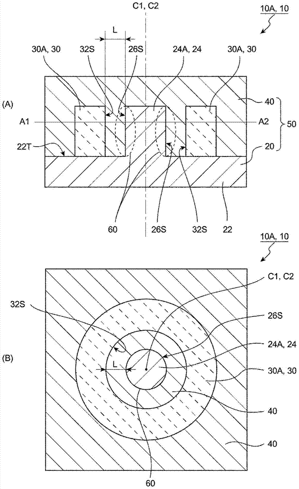
[0075] figure 1 It is a schematic diagram which shows an example of the magnetic element manufactured by the manufacturing method of the magnetic element of this embodiment. here, figure 1 (A) is a schematic cross-sectional view when the magnetic element is cut along a plane including the central axis of the core part of the first magnetic core member, figure 1 (B) is the plane that intersects the magnetic element perpendicular to the central axis of the core ( figure 1 (A) A schematic side view when the symbol A1-A2) is cut off.

[0076] figure 1 The shown magnetic element 10 has a first magnetic core part 20, a winding part 30A (30), and a second magnetic core part 40, wherein the first magnetic core part 20 has a substantially plate-shaped base part 22 and The core portion 24A ( 24 ) protruding from the substantially central portion of one surface (upper surface 22T) of the base portion 22 and the wire winding portion 30A ( 30 ) are formed into a cylindrical body by win...


PUM


Abstract

The magnetic element has a first core member, a winding part, and a second core member, and is manufactured by way of at least a winding part placement step of placing the winding part on the face of the first core member on the side on which the core part is provided, such that the core part is positioned within the inner periphery of the winding part, and an injection molding step of injection molding so as to surround the first core member and the winding part with resin material, and in the winding part placement step, the winding part is placed on the face of the first core member on the side on which the core part is provided, with at least a portion of the inner peripheral face of the winding part distanced from the outer peripheral face of the core part.

Description

technical field [0001] The invention relates to a manufacturing method of a magnetic element and the magnetic element. Background technique [0002] In a magnetic element having a core made of a sintered ferrite core and a coil (winding part) on which a wire is wound around the core, there is a defect or breakage in the core and a closed magnetic circuit is formed. Problems such as complication in assembly. In order to solve such problems, Patent Document 1 proposes a method of manufacturing a magnetic resin molded coil (magnetic element) in which a coil is embedded in a magnetic resin mold. [0003] In this technique, a magnetic resin molded coil is manufactured through a first molding process of injecting a magnetic resin into the inside of the coil or in a portion corresponding to the inside of the coil, and a second molding process. Molding, the second molding process refers to: before or after the first molding process, the magnetic resin is mainly injected into the c...

Claims


Application Information

Patent Timeline
Patent Type & Authority Applications(China)
IPC IPC(8): H01F41/04H01F41/06H01F17/04
CPCH01F17/043H01F2017/048H01F41/0246H01F41/02H01F17/045H01F27/24H01F27/306Y10T29/49073H01F5/00H01F41/04
Inventor 坂本晋一
Owner SUMIDA CORP
Why Eureka
Try Eureka