High rigidity compound processing machine

A compound processing and high rigidity technology, applied in the direction of metal processing machinery parts, metal processing equipment, manufacturing tools, etc., can solve the problems of weak rigidity, low rigidity, long distance, etc., to reduce shaking, improve overall rigidity, and improve processing accuracy Effect

Active Publication Date: 2016-09-14
DN SOLUTIONS CO LTD
View PDF9 Cites 0 Cited by
  • Summary
  • Abstract
  • Description
  • Claims
  • Application Information

AI Technical Summary

Problems solved by technology

[0009] However, in the conventional column-moving type compound processing machine, the machining axis (200') is located on the upper part of the column (100'), so when the column (100') is moved to the high center of gravity (G), rolling (horizontal shaking) occurs. , rolling) and pitching (up and down shaking, pitching), because the distance between the center of gravity (G) of the column (100') and the Y-axis guide rail (Y1', Y2') is long, there is a loop (loop, in the steady vibration Or the place where the displacement is the largest in the standing wave) the problem of weak rigidity
[0010] In addition, in the conventional column-moving type combined processing machine, since the plate-structured Z-axis saddle (300') is thinner than the structure on the column (100'), there may be a problem of low rigidity.
In order to improve this, as shown in the figure, there is a design restriction that a plurality of, for example, three Z-axis guide rails (Z1', Z2', Z3') need to be provided.

Method used


Image

  • High rigidity compound processing machine
  • High rigidity compound processing machine
  • High rigidity compound processing machine

Examples


Embodiment Construction

[0041] Next, a high-rigidity compound processing machine according to an embodiment of the present invention will be described with reference to the drawings.

[0042] In the following description, the "longitudinal direction" refers to the left-right direction or the Z-axis direction when the multi-function processing machine is viewed from the front. The "vertical direction" means the vertical direction or the X-axis direction perpendicular to the Z-axis of the multifunctional processing machine. The "front-rear direction" is perpendicular to the Z-axis and the X-axis of the multifunctional processing machine and refers to the depth direction or the Y-axis direction when the multifunctional processing machine is viewed from the front.

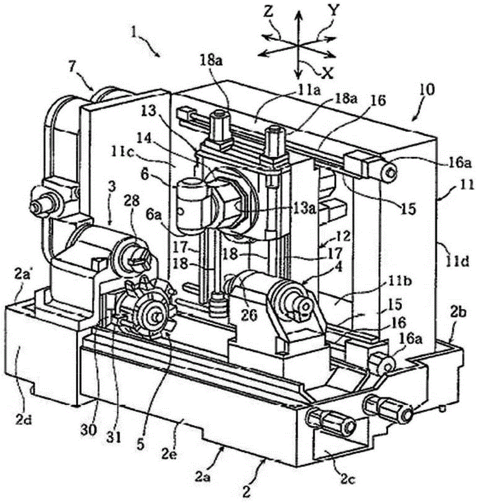
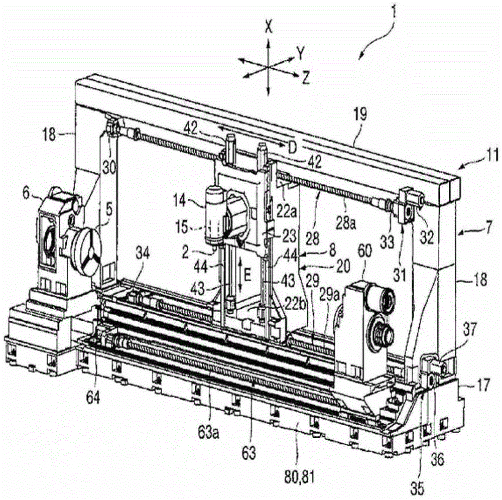
[0043] Figure 2a It is a structural diagram of the high-rigidity compound processing machine of the embodiment of the present invention.

[0044] like Figure 2a As shown, the composite processing machine according to the embodiment of th...


PUM


Abstract

An embodiment of the present invention relates to a high-rigidity compound processing machine. By having a structure in which the shaft structure is close to the center of the column, rolling and pitching can be reduced, and in order to increase rigidity, a Steps are formed, and it is characterized in that it includes: a machine tool (400), which has Z-axis guide rails (Z1, Z2) formed on the upper surface along the length direction; a saddle (300), which is vertical to the length direction. Y-axis guide rails (Y1, Y2) are formed on the upper surface, and the lower surface is configured in a shape corresponding to the upper surface of the machine tool (400). Along the Z-axis guide rails (Z1, Z2) in the transfer in the length direction; the upright column (100), which is formed with X-axis guide rails (X1, X2) in the vertical direction perpendicular to the length direction, and the upright column (100) is arranged on the saddle (300) The upper part is transferred in the front-rear direction along the Y-axis guide rails (Y1, Y2); and the machining axis (200), which is arranged in front of the column (100), moves along the X-axis guide rails (X1, X2) Lifting and lowering, the Y-axis guide rails (Y1, Y2) are disposed at positions spaced upward by a predetermined distance from the lower end of the saddle (300).

Description

technical field [0001] Embodiments of the present invention relate to a composite processing machine, and more specifically, to a high-rigidity composite processing machine capable of reducing rolling and pitching by having a structure in which the shaft is brought close to the center of the column. ) and has a stepped structure at the saddle for increased rigidity. Background technique [0002] In general, a compound processing machine refers to a multi-spindle machine tool capable of both turning and milling, and can perform turning or milling depending on the type of tool attached to the spindle. [0003] This type of compound processing machine includes a three-axis linear transfer structure (X, Y, Z axis) and an axis (B axis) capable of tilting movement on the column in the height direction, and has a side for fixing the workpiece. Turning spindle. [0004] The driving method of the compound processing machine is divided into a ram moving method and a column moving me...

Claims


Application Information

Patent Timeline
Patent Type & Authority Patents(China)
IPC IPC(8): B23P23/02B23B5/00B23C3/00B23Q1/70
CPCB23Q1/017B23B3/065B23P23/02
Inventor 河贤杓
Owner DN SOLUTIONS CO LTD
Why Eureka
Try Eureka