
Method and device for the optical non-contact oscillation measurement of an oscillating object

A non-contact, vibration measurement technology, used in measuring devices, measuring ultrasonic/sonic/infrasonic waves, instruments, etc.

Active Publication Date: 2014-01-01
POLYTEC
View PDF4 Cites 7 Cited by
  • Summary
  • Abstract
  • Description
  • Claims
  • Application Information

AI Technical Summary

Problems solved by technology

Vibration measurements can fail in this way, i.e. when, for example, temperature influences from the environment cause the laser to be in a mode where measurements cannot be made

Method used


Image

  • Method and device for the optical non-contact oscillation measurement of an oscillating object
  • Method and device for the optical non-contact oscillation measurement of an oscillating object
  • Method and device for the optical non-contact oscillation measurement of an oscillating object

Examples


Embodiment Construction

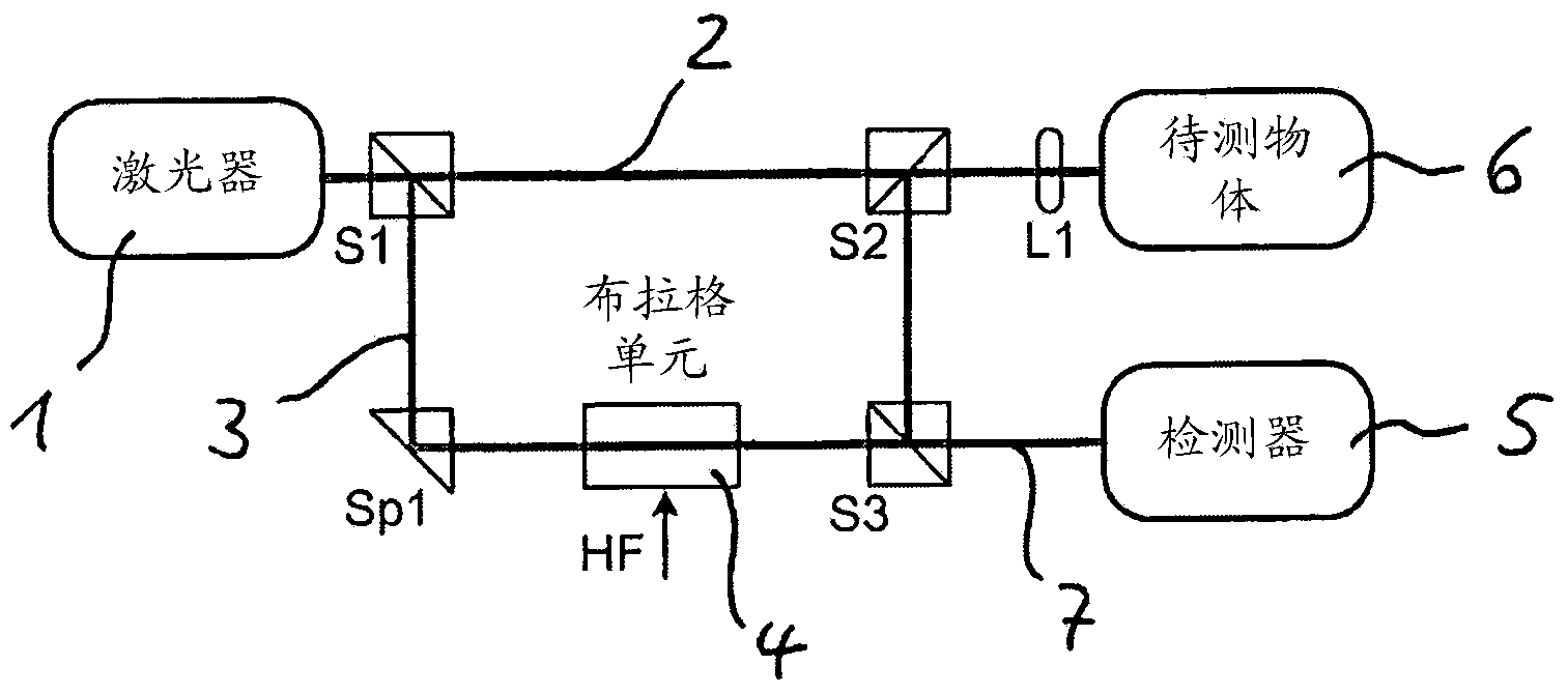
[0029] As an embodiment of the device of the present invention, a device comprising a laser Doppler vibrometer is described here, which in principle is as follows Figure 1a constituted as shown. In the present exemplary embodiment, a He-Ne laser 1 with a resonator length of 20.4 cm is used, the coherent light of which is split into a measuring beam 2 and a reference beam 3 by means of a first beam splitter S1 . The reference beam 3 is guided via the mirror Sp1 through the Bragg cell 4 , which here acts as an acousto-optic frequency instrument, and through a further beam splitter S3 to the optical detector 5 . The Bragg unit 4 then shifts the frequency of the reference signal 3 by typically 40 MHz.

[0030] Measuring beam 2 is conducted via second beam splitter S2 and λ / 4 plate L1 to vibrating test object 6 . The surface of the object 6 to be measured scatters back the measurement beam 2 . The returned measuring beam is reflected in the second (polarizing) beam splitter S2 t...


PUM


Abstract

The invention relates to a device for the optical non-contact oscillation measurement of an oscillating object, comprising a laser Doppler vibrometer that has a laser (1) as the light source for a laser beam, a first beam splitter assembly (S1) for splitting the laser beam into a measuring beam (2) and a reference beam (3), a means (4) for shifting the frequency of the reference beam (3) or of the measuring beam (2) in a defined manner, a second beam splitter assembly (S2, S3) by means of which the measuring beam (2) back-scattered by the oscillating object (6) is merged with the reference beam (3) and superimposed on the same, and a detector (5) for receiving the superimposed measuring and reference beam (7) and for generating a measurement signal, wherein the laser (1) is provided with a polarization filter arranged inside the optical resonator of the laser and the frequency of the dominating mode can be kept constant by a control to the beat signal.

Description

technical field [0001] The invention relates to a non-contact optical vibration measuring device for vibrating objects according to the preamble of claim 1 and a corresponding method according to the preamble of claim 7 . Background technique [0002] Such methods use and such devices include laser Doppler vibrometers with a laser as light source for the laser beam. The laser is split into a measurement beam and a reference beam in the first beam splitting module. Either the measuring beam or the reference beam undergoes a frequency shift, for which purpose acousto-optic modulators, in particular Bragg cells, are usually used. The measuring beam is directed at the object to be measured and scattered or reflected therefrom. The second beam splitter combines the measurement beam scattered back by the vibrating object with the reference beam and superimposes the two beams, whereby an interference signal is obtained. The superimposed measuring and reference beams are fed to a...

Claims


Application Information

Patent Timeline
IPC IPC(8): G01H9/00
CPCG01H9/00
Inventor 克里斯蒂安·伦贝亚历山大·德雷本施泰特马西亚斯·许斯勒克里斯蒂安·埃尔曼福尔克马·罗思
Owner POLYTEC
Learn More