
Synchrocyclotron

A cyclotron, radius technology, applied in magnetic resonance accelerators, accelerators, electrical components, etc., can solve problems such as short distance between accelerating electrodes and transmission lines, adverse effects, and difficulty in designing cyclotrons

Inactive Publication Date: 2014-01-01
ION BEAM APPL
View PDF7 Cites 4 Cited by
  • Summary
  • Abstract
  • Description
  • Claims
  • Application Information

AI Technical Summary

Problems solved by technology

However, increasing the magnetic field beyond 6 tesla, as proposed in the aforementioned patent, has adverse effects
Therefore, it becomes impossible or very difficult to design the central region of the cyclotron because the very high magnetic field causes the radius of the first orbit that the particles follow to be reduced so that the particles cannot bypass the ion source in the first loop
The second disadvantage of magnetic fields above 6 Tesla is that the implementation of the extraction device becomes very complicated
A third disadvantage of magnetic fields above 6 Tesla in the center of the cyclotron is that for such fields the magnetic fields in the coils exceed those for which niobium-titanium alloys can be used
This lack of space requires a short distance between the accelerating electrode and the transmission line, thereby increasing the capacitance (capacité) between these two elements

Method used


Image

  • Synchrocyclotron
  • Synchrocyclotron
  • Synchrocyclotron

Examples


Embodiment Construction

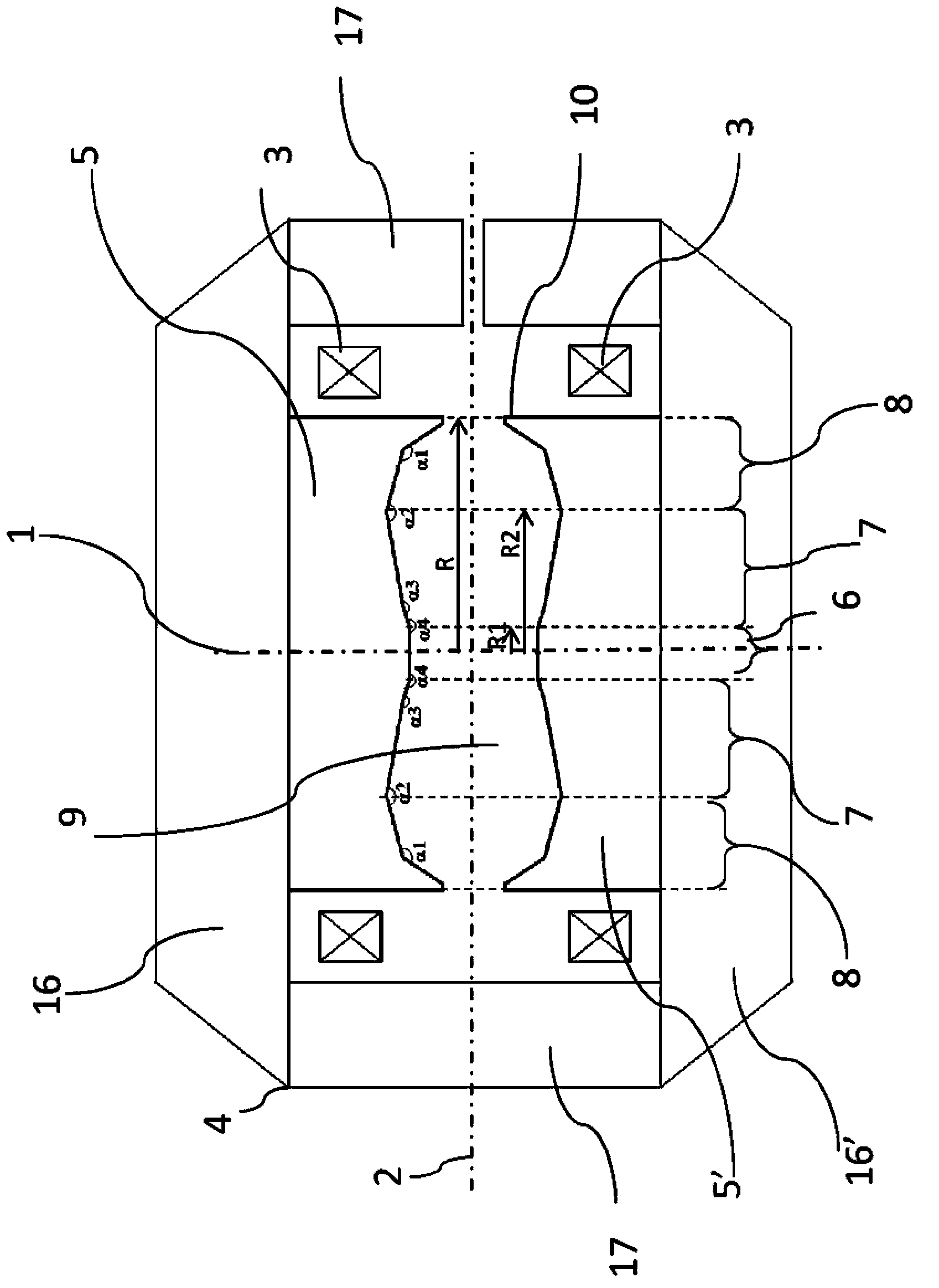
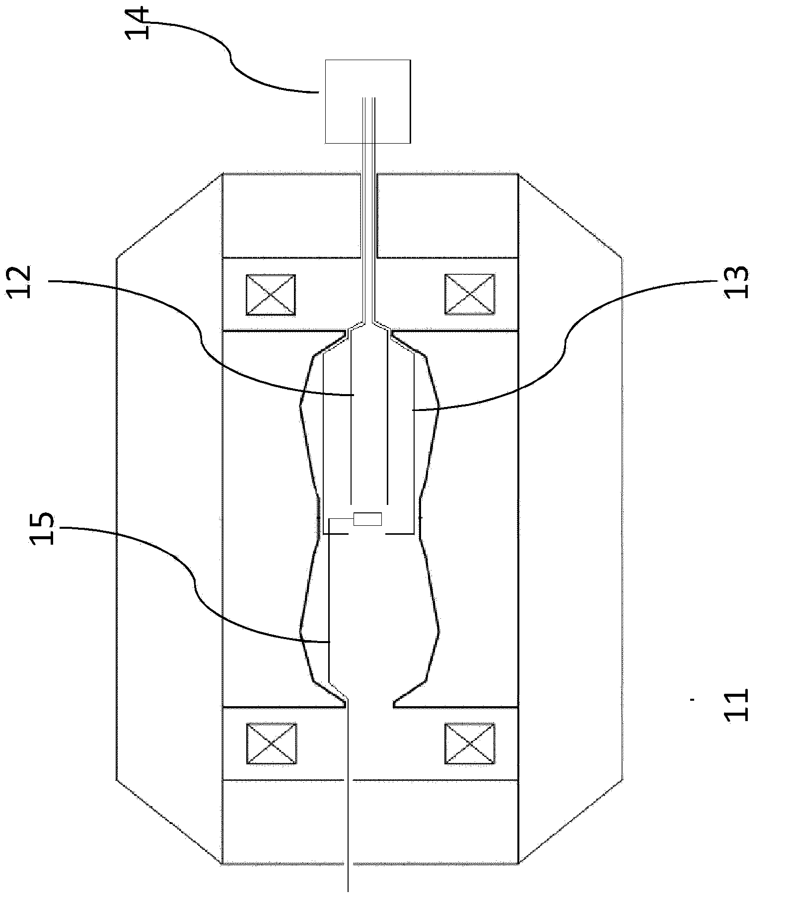
[0036] figure 1 and 2 A synchrocyclotron according to the invention is schematically shown. It should be noted that certain components of the synchrocyclotron are not shown for clarity of the drawings.

[0037] The synchrocyclotrons shown in the accompanying drawings for non-limiting illustration of the present invention include:

[0038] - Ferromagnetic structure 4, the ferromagnetic structure includes:

[0039] o two base plates, also called yoke plates 16, 16', in the form of discs, arranged coaxially with respect to the central axis 1 of the synchrocyclotron, substantially symmetrical and parallel with respect to the central plane 2;

[0040] o A pair of magnetic poles 5, 5' having a generally circular cross-section with a radius R, arranged on either side of the midplane 2 of the synchrocyclotron, centered on the central axis 1, formed by the cavity 9 separated by an air gap; and

[0041] o a magnetic flux return (retour de flux) 17, which surrounds the poles 5, 5' ...


PUM


Abstract

A synchrocyclotron comprises a ferromagnetic structure (4) with a pair of poles (5, 5'), which have a generally circular cross section of radius R which are placed on either side of a mid-plane (2) and centred on a central axis (1). These poles (5, 5') are separated by a gap forming a cavity (9) having a profile substantially symmetrical with respect to the mid-plane (2). The height of this gap varies radially and the profile of the gap comprises, in succession, starting from the central axis (1): a first portion (6, 7) of circular section with a radius R2, which is centred on the central axis (1), the height of the gap at the centre thereof being equal to Hcentre, and which includes an annular subportion (7) in which the height of the gap progressively increases up to a maximum height Hmax at the radius R2, and a second portion, of annular section (8), which surrounds the first portion (6, 7) and in which the height of the gap progressively decreases down to a height Hedge at the edges of the poles (5, 5'). The height Hcentre is greater than 10 cm and the ratio of the maximum height Hmax to the height Hcentre is between 1.1 and 1.5.

Description

technical field [0001] The present invention relates to synchrocyclotrons. Background technique [0002] A synchrocyclotron, like a cyclotron, is a particle accelerator with a magnet structure with two magnetic induction coils radially surrounding a cavity for particle acceleration between two magnetic poles with a central axis, the center plane extends in the cavity perpendicularly to said center axis. Particles are produced in a particle source located near the central axis in the cavity, and are discharged from the particle source so that the accelerating electrode powered by a high-frequency AC voltage generator is accelerated along a helical trajectory in the central plane. Such synchrocyclotrons are increasingly being used in hadron therapy. [0003] Unlike a cyclotron where particles are accelerated at the same frequency, in a synchrocyclotron the frequency of the electric field applied to the accelerating electrodes is modulated to compensate for the increase in re...

Claims


Application Information

Patent Timeline
Patent Type & Authority Applications(China)
IPC IPC(8): H05H7/04H05H13/02
CPCH05H7/04H05H13/02
Inventor J·芒德里永M·孔雅
Owner ION BEAM APPL
Learn More