RF system for synchrocyclotron

a radiofrequency and synchrocyclotron technology, applied in the field of synchrocyclotrons, can solve the problems of affecting the proper operation of the capacitor, affecting the reliability affecting the efficiency of the cooling system, so as to improve the absorbance of thermal radiation emitted, improve the cooling system, and reduce the effect of cos

Active Publication Date: 2016-05-24
ION BEAM APPL
View PDF7 Cites 0 Cited by
  • Summary
  • Abstract
  • Description
  • Claims
  • Application Information

AI Technical Summary

Benefits of technology

[0008]Such an RF system indeed makes it possible to increase the transfer of heat in the form of radiation from the rotor to the conducting enclosure, thus allowing better cooling of the rotor. This is particularly advantageous when the rotor rotates at high speeds, such as for example speeds greater than 5000 revolutions per minute.
[0010]Such a configuration makes it possible to improve the absorbance of the thermal radiation emitted by the exterior surface of the exterior layer of the rotor and thus to cool the rotor even better.
[0011]In a preferential manner, the RF system according to the invention does not comprise any means for cooling the rotor by forced convection of a fluid which would be in direct contact with the rotor. Such a configuration makes it possible to have a greatly simplified and less expensive RF system, while preserving comparable heat dissipation properties, and allowing the use of this RF system in a synchrocyclotron.

Problems solved by technology

Other causes of heating are the RF currents which traverse the rotor.
Now, this heating causes deformations in the geometry of the rotor, and this may disturb its proper operation.
It can also lead to premature aging of the materials of which the capacitor is composed and / or which are in contact with it.
However, this system requires the manufacture of a complex labyrinthine network of flexible pipes and the addition of air blowers and a system for evacuating this air.
Such cooling systems are complex, expensive, and often rather unreliable.
These known cooling means are moreover increasingly difficult and expensive to implement as RF powers increase and / or the rotation speed of the rotor increases, this being the case in the synchrocyclotrons which are undergoing development and which are aimed at increasing the number of packets of particles that they can produce per unit time.

Method used


Image

  • RF system for synchrocyclotron
  • RF system for synchrocyclotron
  • RF system for synchrocyclotron

Examples


Embodiment Construction

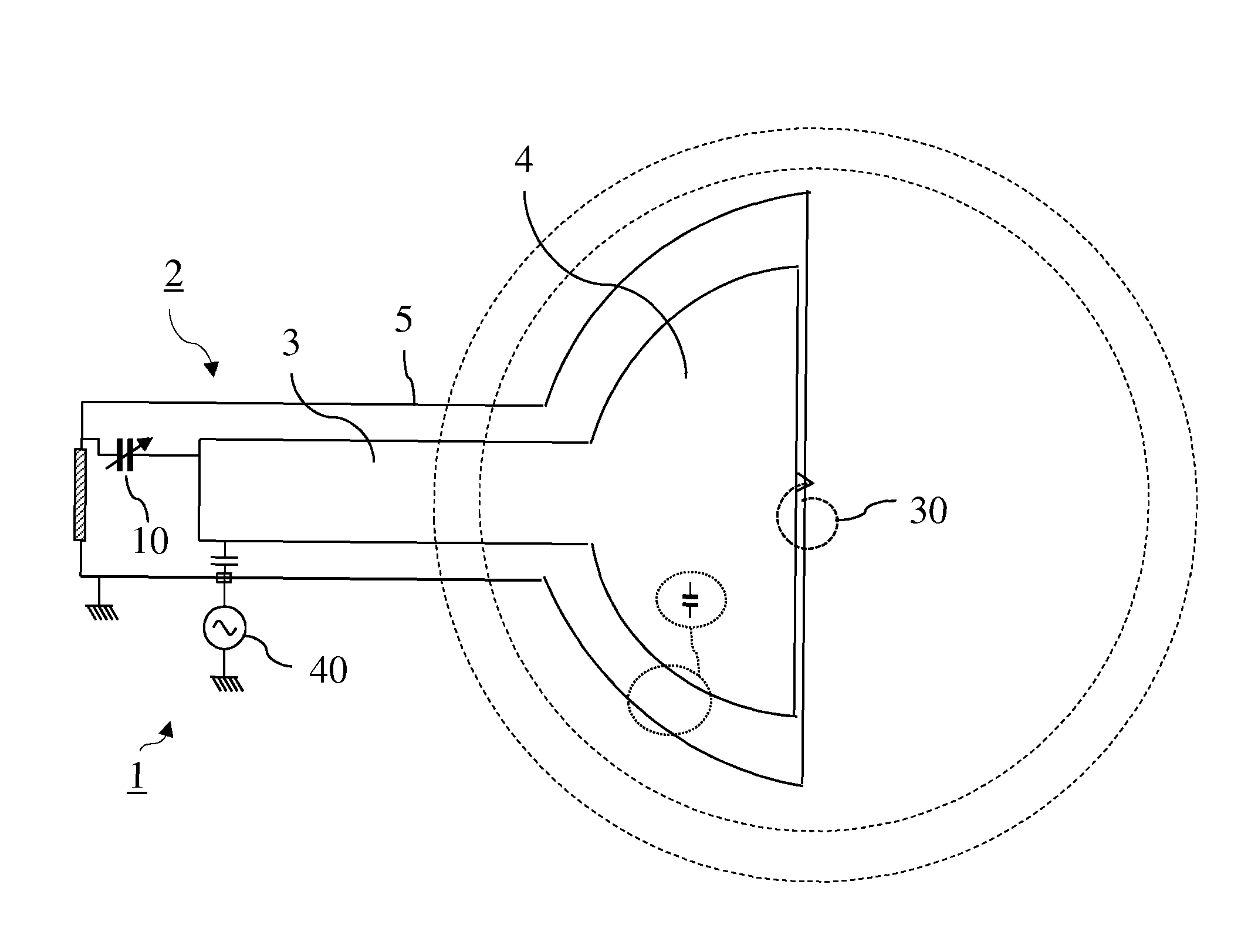
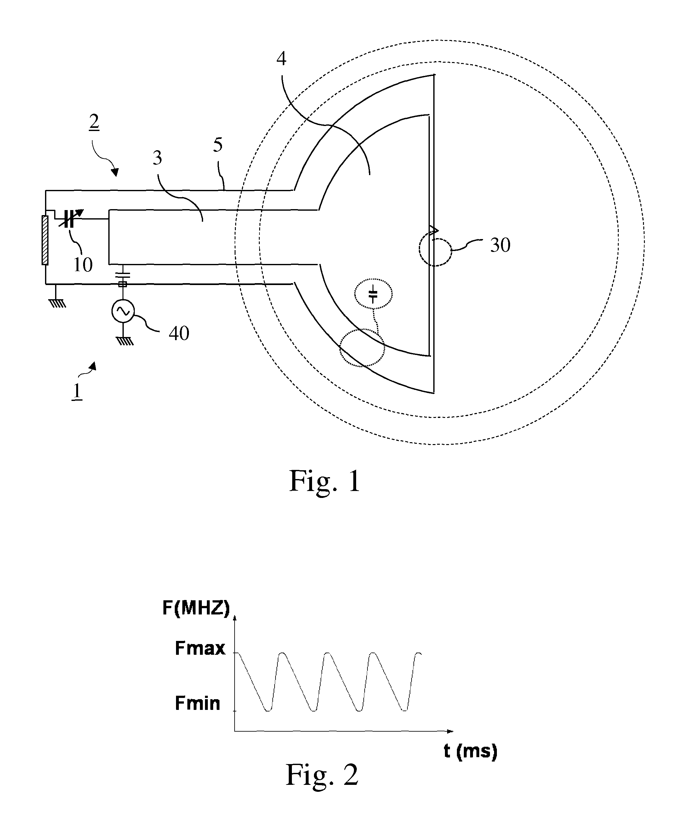
[0027]Note that within the framework of the present invention, “RF” should be understood to mean a radiofrequency, that is to say a frequency lying between 3 KHz and 300 GHz. In a synchrocyclotron, this frequency varies for example between 59 MHz and 88 MHz.

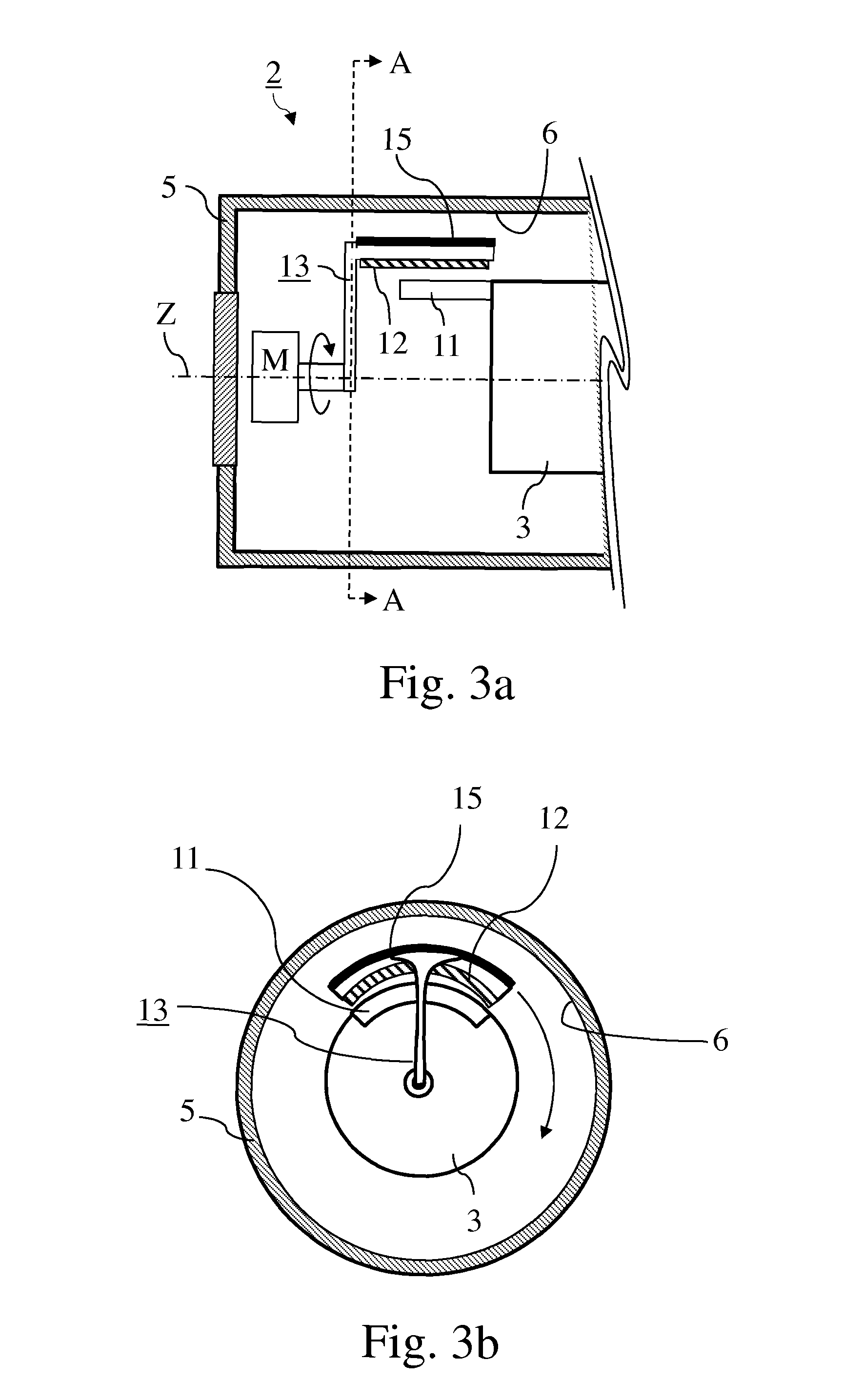
[0028]FIG. 1 represents firstly in a general and schematic way an RF system (1) according to the invention. This RF system includes a resonant cavity (2) comprising a conducting enclosure (5) within which are placed a conducting pillar (3) of which a first end is linked to an accelerating electrode (4) able to accelerate the charged particles along a desired trajectory (30) in the synchrocyclotron, a rotary variable capacitor (10) (also called a “rotco”) coupled between a second end opposite from the first end of the pillar (3) and the conducting enclosure (5) and whose variable capacitance is able to vary a resonant frequency of the resonant cavity (2) in a cyclic manner over time. The said variable capacitor (10) comprises fixe...


PUM

PropertyMeasurementUnit
conductivityaaaaaaaaaa
total emissivityaaaaaaaaaa

Abstract

The present invention relates to an RF system (1) able to generate a voltage for accelerating charged particles in a synchrocyclotron, the RF system (1) including a resonant cavity (2) comprising a conducting enclosure (5) within which are placed a conducting pillar (3) of which a first end is linked to an accelerating electrode (4) able to accelerate the charged particles, a rotary variable capacitor (10) coupled between a second end opposite from the first end of the pillar (3) and the conducting enclosure (5), the said capacitor (10) comprising fixed electrodes (11) and a rotor (13) comprising mobile electrodes (12), the fixed electrodes (11) and the mobile electrodes (12) forming a variable capacitance able to vary a resonant frequency of the resonant cavity (2) in a cyclic manner over time, an exterior layer of the rotor (13) having a conductivity of greater than 20,000,000 S / m at 300 K. At least one part of the exterior surface (15) of the rotor (13) is a surface possessing a normal total emissivity of greater than 0.5 and less than 1, thereby allowing better cooling of the rotor and / or making it possible to dispense with a system for cooling the rotor by conduction and / or by convection.

Description

CROSS-REFERENCE TO RELATED APPLICATIONS[0001]This application is a national stage entry under 35 U.S.C. §371 of International Application No. PCT / EP2012 / 072682, filed Nov. 15, 2012, which claims the benefit of priority of European Application No. 11189533.0, filed Nov. 17, 2011, and U.S. Provisional Patent Application No. 61 / 560,907, filed Nov. 17, 2011, the disclosures of which are hereby incorporated by reference herein in their entirety.FIELD OF THE INVENTION[0002]The present invention pertains to the field of synchrocyclotrons. More particularly, the invention relates to a radio-frequency (RF) system able to generate a voltage for accelerating charged particles in a synchrocyclotron, the RF system including a resonant cavity comprising a conducting enclosure within which are placed a conducting pillar of which a first end is linked to an accelerating electrode able to accelerate the charged particles, and a rotary variable capacitor coupled between a second end opposite from the...

Claims


Application Information

Patent Timeline
Patent Type & Authority Patents(United States)
IPC IPC(8): H05H7/02H05H13/02
CPCH05H13/02H05H7/02H05H2007/025Y10T29/49117
Inventor VERBRUGGEN, PATRICK
Owner ION BEAM APPL
Why Eureka
Try Eureka