Improved water dispenser

A water dispenser and water inlet pipe technology, applied in beverage preparation devices, household appliances, applications, etc., can solve problems such as scalding children, power consumption, and children touching the faucet, and achieve the effect of preventing accidental burns

Inactive Publication Date: 2014-01-08
CIXI ZHUOYUE ELECTRIC APPLIANCE
View PDF0 Cites 3 Cited by
  • Summary
  • Abstract
  • Description
  • Claims
  • Application Information

AI Technical Summary

Problems solved by technology

[0002] At present, the inner cavity pressure of the heating tank of the energy-saving water dispenser in the prior art is relatively high, which may easily cause water leakage in the heating tank. Since the heating tank needs to withstand relatively high pressure, the manufacturing process and material quality of the heating tank must be affected. They all have high requirements, and the heating liner generally cools down quickly after the power is turned off, so it needs to be connected to the power for a long time, and it consumes electricity when it is not in use.
In addition, the faucet of the existing water dispenser is easily touched by children, especially the hot water faucet, which will cause children to be scalded

Method used


Image

  • Improved water dispenser

Examples


Embodiment 1

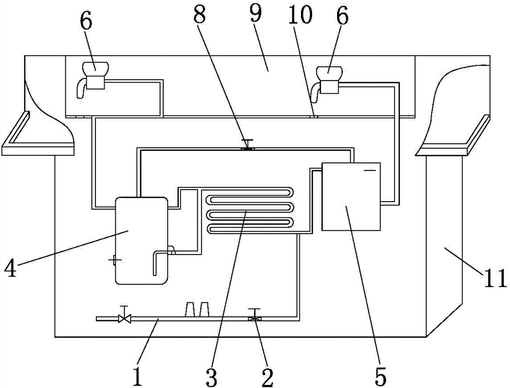
[0022] like figure 1 As shown, an improved water dispenser includes a casing 11, a water inlet pipe 1 is arranged in the casing 11, an electromagnetic valve 2 is connected to the output end of the water inlet pipe 1, and a heat exchanger 3 is connected to the output end of the electromagnetic valve 2. The two ends of the device 3 are respectively connected with a heating inner tank 4 and a warm water storage tank 5, and the output ends of the heating inner tank 4 and the warm water storage tank 5 are connected with a faucet 6. The upper ends of the heating inner tank 4 and the warm water storage tank 5 are respectively provided with The air outlet and the air inlet are connected with a ventilation pipe 7 between the air outlet and the air inlet, and the ventilation pipe 7 is connected with an induction air release valve 8, and the inner walls of the heating inner tank 4 and the warm water storage tank 5 are provided with thermal insulation layers, The casing 11 is provided wit...

Embodiment 2

[0024] In this embodiment, one end of the induction air release valve 8 is connected with a air release pipe, a float ball is arranged in the induction air release valve 8, the float ball can limit the way the gas flows out, and the bottom of the groove is provided with a corresponding faucet 6 The water outlet 10 is also hidden in the casing 11 .

[0025] In this embodiment, the lower part of the casing 11 is provided with a water receiving box corresponding to the lower part of the faucet 6, and the upper end of the water receiving box is provided with a dustproof plate that can be opened and closed. Leakage, you can open it to let the water leak into the water receiving box; when the water is finished or not in use, the dust cover can be set on the water receiving box to prevent bacteria from entering the water receiving box. , fermented and deteriorated, so as to ensure the cleanliness of the water outlet.

[0026] In this embodiment, the bottom end of the casing 11 is pr...

Embodiment 3

[0029] In this embodiment, the water faucet 6 is provided with an inclined water outlet 10 inside, the water outlet 10 is provided with a baffle plate, the lower end of the baffle plate is provided with a spring, and the upper end of the baffle plate is hinged with a handle, so that the water flow can be effectively controlled. size.

[0030] In this embodiment, the water tap 6 is provided with a detachably connected water outlet plug. The water outlet plug is in the shape of a mesh or a funnel. The detachable water outlet plug is installed in the water faucet 6, mainly to control the direction of the water flow. Prevent boiling water from splashing when pouring water.


PUM


Abstract

The invention relates to the technical field of water drinking equipment and tools, in particular to an improved water dispenser. The improved water dispenser comprises a machine shell, a water inlet pipe, an electromagnetic valve, a heat exchanger, a heating inner container and a warm water storage tank, wherein the output end of the heating inner container and the output end of the warm water storage tank are respectively provided with a tap, the upper end of the heating inner container and the upper end of the warm water storage tank are provided with an air outlet and an air inlet respectively, a ventilation pipe is connected between the air outlet and the air inlet, the ventilation pipe is connected with an induction release valve, the inner wall of the heating inner container and the inner wall of the warm water storage tank are respectively provided with a heat-preserving layer, the positions, corresponding to the taps, of the machine shell are provided with grooves, the taps are arranged in the grooves, and the outer wall of the machine shell is provided with a cover plate connected with the machine shell in a matched and buckled mode. The improved water dispenser is provided with the air outlet, the air inlet and the ventilation pipe, so pressure borne by the heating inner container can be reduced; the heat-preserving layer enables water in the heating inner container to keep warm for a long time, and electricity is saved; the positions, corresponding to the taps, of the machine shell are provided with the grooves, and accordingly the taps can be hidden and accidental scalding is avoided.

Description

technical field [0001] The invention relates to the technical field of drinking water equipment, in particular to an improved drinking water machine. Background technique [0002] At present, the inner cavity pressure of the heating tank of the energy-saving water dispenser in the prior art is relatively high, which may easily cause water leakage in the heating tank. Since the heating tank needs to withstand relatively high pressure, the manufacturing process and material quality of the heating tank must be affected. They all have high requirements, and the heating liner generally cools down quickly after the power is cut off, so it needs to be connected to the power for a long time, and it consumes electricity when it is not in use. In addition, the faucet of the existing water dispenser is easily touched by children, especially the hot water faucet, which may cause scald children. Contents of the invention [0003] The purpose of the present invention is to address the ...

Claims


Application Information

Patent Timeline
Patent Type & Authority Applications(China)
IPC IPC(8): A47J31/00A47J31/54A47J31/50A47J31/44A47J31/46
Inventor 沈秀萍
Owner CIXI ZHUOYUE ELECTRIC APPLIANCE
Why Eureka
Try Eureka