Installation structure of jointless conductive nickel ring

A technology of installation structure and nickel ring, which is applied in the direction of furnace, heat treatment equipment, heat treatment furnace, etc., can solve problems such as easy shaking, unguaranteed outer circle size, scrapped nickel ring, etc., to improve work reliability and quality of outlet , The effect of simplifying the structure of parts

Inactive Publication Date: 2014-01-08
JIANGSU NANHAI CABLE EQUIP
View PDF2 Cites 2 Cited by
  • Summary
  • Abstract
  • Description
  • Claims
  • Application Information

AI Technical Summary

Problems solved by technology

The disadvantages of the existing open-type conductive nickel ring after installation are: because the interface of the open-type conductive nickel ring is difficult to handle, the appearance is rough and uneven, the outer circle size cannot be guaranteed, the circle is serious, and the wiring is not good when the power is on. Stable, easy to shake, spark, lead to surface quality defects of annealed copper wire, disconnection and other problems, will accelerate the uneven wear of the conductive nickel ring, resulting in early scrapping of the nickel ring
At the same time, the installation structure of the existing open-type conductive nickel ring is also difficult to disassemble when the nickel ring is replaced, and it is easy to damage the contact surface between the contact copper wheel and the conductive nickel ring, which affects the conductive effect.

Method used


Image

  • Installation structure of jointless conductive nickel ring

Examples


Embodiment Construction

[0008] The specific content of the present invention will be described in detail below in conjunction with the accompanying drawings and specific embodiments.

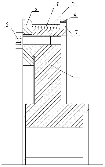
[0009] like figure 1 As shown, the installation structure of the non-interface conductive nickel ring includes: a contact copper wheel 1, a contact wheel cover 3 connected to the contact copper wheel 1 through a connecting screw 2, and the contact wheel 4 on the outer edge 4 of the contact copper wheel 1. A wiring groove 5 is formed between the outer sides of the wheel cover 3, and there is a non-interface conductive nickel ring 6 in the wiring groove 5 outside the contact copper wheel 1, and the two ends of the non-interface conductive nickel ring 6 are connected to the contact wheel cover 3 respectively. The outer side and the outer edge 4 of the contact copper wheel 1 are offset, and some disassembly process screw holes 7 are arranged on the outer edge 4 of the contact copper wheel 1.

[0010] When the above-mentio...


PUM


Abstract

The invention discloses an installation structure of a jointless conductive nickel ring, which has a long service life. The installation structure comprises a contact copper wheel and a contact wheel cover which is connected with the contact copper wheel by a connecting bolt; a wiring duct is formed between the outer edge of the contact copper wheel and the outer side of the contact wheel cover; the jointless conductive nickel ring is arranged in the wiring duct outside the contact copper wheel; the two ends of the non-interface conductive nickel ring respectively abut against the outer side of the contact wheel cover and the outer edge of the contact copper wheel; and a plurality of dismounting process screw holes are formed in the outer edge of the contact copper wheel.

Description

technical field [0001] The invention relates to an accessory of a wire annealing machine, in particular to an installation structure of a conductive nickel ring used on the wire annealing machine. Background technique [0002] The wire annealing machine is a common copper wire annealing equipment, and the outer ring of the contact copper wheel of the wire annealing machine is provided with a conductive nickel ring. Since the conductive nickel ring is a vulnerable part, it needs to be purchased and replaced by the user. At present, open-type conductive nickel rings are used on both domestic and imported wire annealing machines. Since the thickness of the conductive nickel ring is small, generally about 2 mm, the existing conductive nickel rings are all made of nickel strips through machining. The interface needs to be polished. If the treatment is not good, the appearance is rough and uneven. The outer circle size cannot be guaranteed, and the roundness is serious. Duri...

Claims


Application Information

Patent Timeline
Patent Type & Authority Applications(China)
IPC IPC(8): C21D9/52
Inventor 李建文任金海
Owner JIANGSU NANHAI CABLE EQUIP
Why Eureka
Try Eureka