Electronic limit control system and method for speed reducer

A technology of electronic limit control and reducer, applied in the direction of use feedback control, etc., can solve problems such as complicated installation, troublesome adjustment, and harsh working environment, and achieve the effects of high positioning accuracy, long service life, and simple on-site debugging

Inactive Publication Date: 2014-01-08
SHANGHAI PUDONG XINGCHUAN MACHINERY MFGCO
View PDF9 Cites 1 Cited by
  • Summary
  • Abstract
  • Description
  • Claims
  • Application Information

AI Technical Summary

Problems solved by technology

[0003] Now all the limit devices of reducers on the market are of mechanical transmission type. It relies on a set of pulleys to drive the screw, and the nut moves the micro switch from transmission to displacement to realize the stop of the reducer at the set position. After many years of realization, this limit device is also an effective mechanism, which can basically meet the use of greenhouse transmission systems. However, its defects are also exposed in production and use: 1. There are many parts, and the whole set of limit devices has More than 30 parts, complex processing and installation, high requirements for installation technology; 2. The adjustment is troublesome, and it needs 2 people to cooperate in the greenhouse site, and it can be completed after repeated times. 3. The operation is not intuitive, only after understanding its transmission principle , can be adjusted, and the technical requirements for the operation, installation and debugging workers are high. 4. As the use time increases, the number of failures in the mechanical transmission system increases, and because there are many parts in the whole set of mechanisms, the problematic links also increase accordingly. 5. The whole set The mechanism is exposed to the high-temperature and high-humidity environment of the greenhouse, and the working environment is harsh, which aggravates the damage of parts, especially the micro switch with poor sealing, bearings and other parts are more likely to be damaged. The transmission system of the greenhouse brings great harm and even causes safety accidents.

Method used


Image

  • Electronic limit control system and method for speed reducer
  • Electronic limit control system and method for speed reducer

Examples


Embodiment Construction

[0023] The preferred embodiments of the present invention will be described in detail below in conjunction with the accompanying drawings, so that the advantages and characteristics of the present invention can be easily understood by those skilled in the art, so as to define the protection scope of the present invention more clearly.

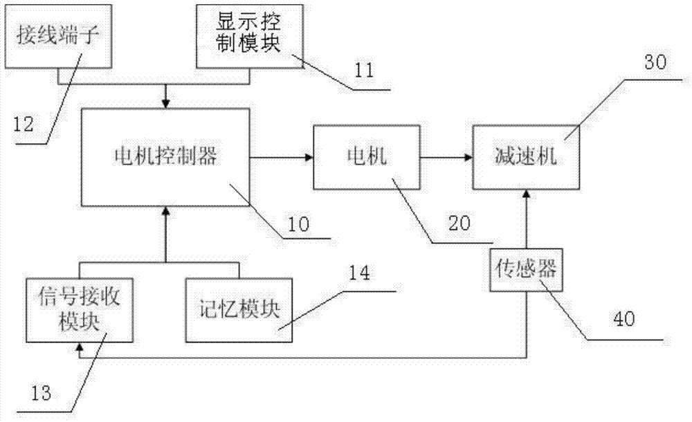
[0024] see Figure 1~2 , an electronic limit control system for a reducer, including a motor 20 and a reducer body 30, the reducer body 30 includes: at least one power input shaft, at least one power output shaft, a first reduction gear set, a second reduction gear set , the power output shaft and the power input shaft are connected through the first reduction gear set, the second reduction gear set is meshed with the first reduction gear set, the motor 20 is connected to the power input shaft of the reducer body 30 through gears, and the motor control The sensor 10 and the sensor 40, the sensor 40 is set in the reducer 30, to receive the pulse...


PUM


Abstract

The invention discloses an electronic limit control system and an electronic limit control method for a speed reducer. The electronic limit control system comprises a motor and a speed reducer body, and is characterized by also comprising a motor controller and a sensor, wherein the sensor is arranged in the speed reducer and is used for receiving a pulse signal sent out by the speed reducer, meanwhile converting the pulse signal into an electric signal and transmitting to the motor controller; the motor controller is used for controlling forward rotation and reverse rotation of the motor. The method comprises the following steps: adjusting the phase sequence of the motor and the sensor; setting a position A and a position B for operation of the motor in a display control module; setting an output path of a motor output shaft; performing limit control over the speed reducer in an electronic limit mode. Since the sensor used in the electronic limit is non-contact, the service life is long, the positioning accuracy is higher, the field debugging is simple, and the operation and stop can be realized at a set starting point and a set end point by debugging once without repeated debugging.

Description

technical field [0001] The present invention relates to a control system and method, in particular to an electronic limit control system and method of a reducer. Background technique [0002] The special deceleration motor widely used in modern greenhouses is an indispensable mechanical equipment for the greenhouse window opening and curtain (inner heat preservation, external sunshade) system. In order to ensure the opening and closing of the window and curtain can be accurately positioned, this type of reducer It is equipped with a limit control device. Through the adjustment of the limit device, the window-opening machinery and curtain-drawing machinery of the greenhouse can rotate in the set area, and can stop and run at the set start point and end point. Satisfy The requirements for temperature, light, shading and heat preservation in the greenhouse ensure the safe operation of the transmission machinery in the greenhouse. [0003] Now all the limit devices of the reduc...

Claims


Application Information

Patent Timeline
Patent Type & Authority Applications(China)
IPC IPC(8): G05D3/12
Inventor 朱骥镛朱静史惠义戴嘉坤王梦雄
Owner SHANGHAI PUDONG XINGCHUAN MACHINERY MFGCO
Why Eureka
Try Eureka