a tree antenna

An antenna and tree-shaped technology, which is applied in the field of miniaturized ultra-wideband antennas, can solve the problems of large logarithmic periodic antenna unit size, unsuitable for installation on airborne platforms, and inability to realize wide bandwidth angular scanning, etc., to achieve horizontal size reduction, The effect of reducing the horizontal size and reducing the footprint

Active Publication Date: 2016-04-06
CHINA ELECTRONIC TECH GRP CORP NO 38 RES INST
View PDF4 Cites 0 Cited by
  • Summary
  • Abstract
  • Description
  • Claims
  • Application Information

AI Technical Summary

Problems solved by technology

[0008] In order to solve problems such as the large size of the conventional log-periodic antenna unit, which is not suitable for installation on the airborne platform and cannot realize wide-bandwidth angular scanning, it is necessary to reduce the size of the conventional log-periodic antenna, especially the size in the width direction. The present invention provides An Improved Tree Log Periodic Antenna

Method used


Image

  • a tree antenna
  • a tree antenna
  • a tree antenna

Examples


Embodiment 1

[0032] see Figure 4 , a preferred embodiment of the present invention is a first-order fractal log-periodic antenna. The antenna includes a first feeder rod 11, a second feeder rod 12 and six pairs of vibrators; the upper ends of the first feeder rod 11 and the second feeder rod 12 are connected to form a herringbone, and the gap between the two feeder rods is The angle 18 between the feed rods is 6 degrees; each pair of vibrators is one level, and the six pairs of vibrators increase step by step from top to bottom; the six pairs of vibrators are all first-order fractal vibrators, which are the first fractal vibrator 1 and the second fractal vibrator respectively. The vibrator 2, the third fractal vibrator 3, the fourth fractal vibrator 4, the fifth fractal vibrator 5 and the sixth fractal vibrator 6 are respectively symmetrically installed on two feeder rods; the structures of the six pairs of vibrators are the same, but the sizes are different. See the specific structure ...

Embodiment 2

[0037] see Figure 5 , another preferred embodiment of the present invention is a second-order fractal log-periodic antenna. The antenna includes a first feeder rod 11, a second feeder rod 12 and four pairs of second-order fractal oscillators, and each pair of second-order fractal oscillators in the four pairs of second-order fractal oscillators is the seventh fractal oscillator 7 and the eighth fractal oscillator respectively. Vibrator 8, ninth fractal vibrator 9, and tenth fractal vibrator 10; the upper ends of the two feed rods are connected to form a herringbone shape, and the angle 18 between the two feed rods is 6 degrees; each pair of two The first-order fractal oscillators are symmetrically installed on two feed rods; each pair of second-order fractal oscillators has the same structure, but different sizes, and the size increases gradually from top to bottom. See the specific structure image 3 , the second-order fractal oscillator includes three first-order fractal ...

Embodiment 3

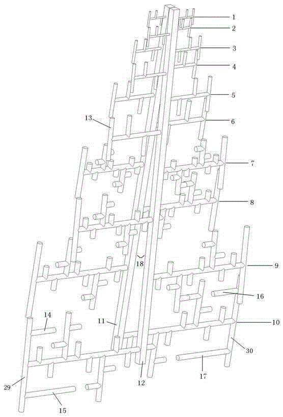
[0043] see figure 1 , another preferred embodiment of the present invention is a logarithmic periodic antenna composed of a first-order fractal oscillator and a second-order fractal oscillator. The antenna includes a first feeding rod 11, a second feeding rod 12, six pairs of first-order fractal oscillators and four pairs of second-order fractal oscillators, and one group of the six pairs of first-order fractal oscillators is the first fractal oscillator 1, the second Fractal oscillator 2, third fractal oscillator 3, fourth fractal oscillator 4, fifth fractal oscillator 5 and sixth fractal oscillator 6, one of the four pairs of second-order fractal oscillators is the seventh fractal oscillator 7, the eighth fractal oscillator 8, The ninth fractal vibrator 9 and the tenth fractal vibrator 10; the upper ends of the two feed rods are connected to form a herringbone shape, and the included angle is the feed rod angle 18; each pair of fractal vibrator is symmetrically installed on...


PUM


Abstract

The invention relates to a tree antenna, which comprises two feed rods and more than three pairs of vibrators, each pair of vibrators is one level, and more than three pairs of vibrators increase step by step from top to bottom; the upper ends of the two feed rods Connected to form a herringbone; each pair of vibrators is symmetrically installed on two feeder rods, and each pair of vibrators has the same structure but different sizes. The vibrator is a first-order fractal vibrator or a second-order fractal vibrator; the fractal vibrator includes three fractal vibrator arms that are sequentially connected in a horizontal rod shape, and a vertical upward fractal vibrator arm or vertical The straight downward fractal oscillator arms have the same length; one end of the three sequentially connected fractal oscillator arms is connected to a feed rod, and the other end is connected to a first-order loaded metal rod. The invention greatly reduces the volume of the antenna, solves the problem that the conventional meter-wave logarithmic period antenna cannot be installed on the airborne platform, reduces the mutual coupling of the antenna, and makes the electrical performance meet the requirements of the system.

Description

technical field [0001] The invention belongs to the technical field of logarithmic periodic antennas for receiving or transmitting ultra-wideband meter-wave band electromagnetic waves, and in particular relates to a miniaturized ultra-wideband antenna. Background technique [0002] Electronic Support Measures (ESM) in the radar band are critical sensors for situational awareness, tactical intelligence, targeting support and threat warning. By intercepting, locating, classifying and identifying specific radar radiation sources, radar ESM can provide combatants with information on the enemy's electronic battle sequence and can effectively identify the enemy, providing details of its position and capabilities. The Electronic Support Measures (ESM) system is an important part of the airborne mission electronic system. Usually the main operational target of the electronic support system is to work at 2-18 GHz, and it has also been extended to 0.5-2 GHz and 18-40 GHz. With the vi...

Claims


Application Information

Patent Timeline
Patent Type & Authority Patents(China)
IPC IPC(8): H01Q1/36H01Q1/50
Inventor 秦浩方佳曹锐臧永东
Owner CHINA ELECTRONIC TECH GRP CORP NO 38 RES INST
Why Eureka
Try Eureka