
A connection structure of the damping ring and the pole piece of a solid magnetic pole salient pole synchronous motor

A synchronous motor, solid magnetic pole technology, applied in the direction of structural connection, electric components, electrical components, etc., can solve the problems of easy generation of sparks, motor repair, melting, etc., to achieve the effect of firm and reliable connection, offset centrifugal force, and sufficient contact

Active Publication Date: 2015-12-23
XIANGTAN ELECTRIC MFG CORP LTD
View PDF6 Cites 0 Cited by
  • Summary
  • Abstract
  • Description
  • Claims
  • Application Information

AI Technical Summary

Problems solved by technology

When the solid magnetic pole salient pole synchronous motor is started, a large current flows through the contact surface of the damping ring and the pole piece, and the current density at the contact surface is high, and sparks are easy to be generated in the poor contact, and the physical contact of two different materials is easy to generate Electric corrosion, both of the above two factors will lead to high temperature at the contact surface, which will partially melt the damping ring and pole piece, making the contact surface more poor. Damping ring and fixing bolt separated from pole piece
The above phenomena will lead to major quality accidents, and motor repairs occur from time to time

Method used


Image

  • A connection structure of the damping ring and the pole piece of a solid magnetic pole salient pole synchronous motor
  • A connection structure of the damping ring and the pole piece of a solid magnetic pole salient pole synchronous motor

Examples


Embodiment Construction

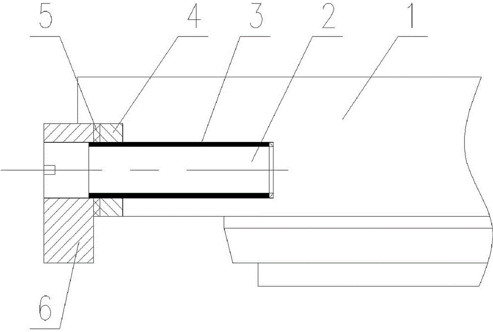
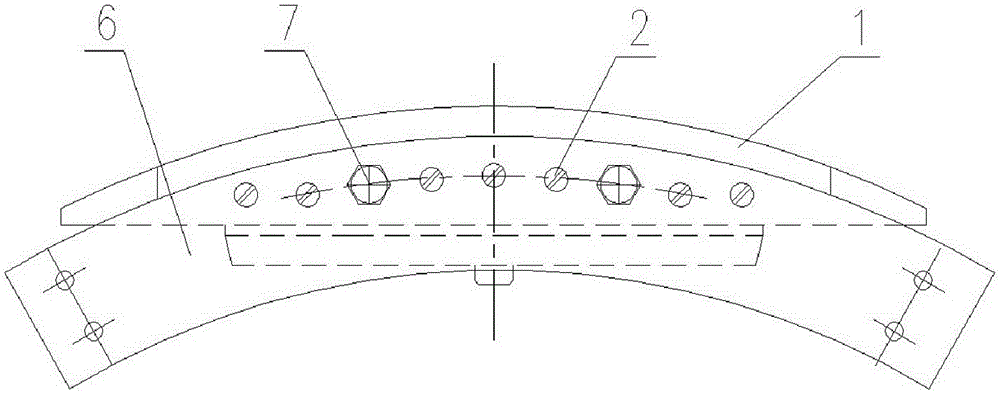
[0012] The present invention will be further described below in conjunction with the accompanying drawings and specific embodiments. A connection structure between a solid magnetic pole salient pole synchronous motor damping ring and a pole shoe includes a pole shoe 1, a conductive connecting screw 2, a conductive paste 3, a copper layer 4, Silver copper solder piece 5, damping ring 6, bolt 7. Process the end face of the pole shoe 1 into a flange and the contact surface with the damping ring 6, weld the copper layer 4 on the contact surface of the pole shoe 1 by welding process, and process the surface of the copper layer 4 to be smooth And guarantee a thickness of 3mm to 5mm. A number of screw holes are processed on the end face of the pole shoe 1 with the copper layer 4, and the conductive paste 3 is applied to the threaded surface of the conductive connecting screw 2, and the threaded end of the conductive connecting screw 2 is tightened on the screw on the end face of the ...


PUM


Abstract

The invention relates to a connecting structure of a damping ring and a pole piece for a solid magnetic pole salient pole synchronous motor. The connecting structure comprises a damping ring and a pole piece which are fixed together by bolts, wherein the end face, in contact with the damping ring, of the pole piece is provided with a copper layer. The end face, in contact with the damping ring, of the pole piece is provided with the copper layer, and accordingly, the copper layer has the same material with the copper damping ring, so the damping ring is in full contact with the copper layer; especially, after being welded together, the copper layer and the damping ring are fixedly connected by the bolts, so that the connection is firm, and the full contact is ensured; in addition, a stopping flange is arranged on the end face of the pole piece, so that the centrifugal force borne by the damping ring is greatly counteracted, and the entire connection is secure and reliable.

Description

technical field [0001] The invention relates to a solid magnetic pole salient pole synchronous motor, in particular to a connection structure between a solid magnetic pole salient pole synchronous motor damping ring and a pole shoe. Background technique [0002] For the traditional solid pole salient pole synchronous motor, the connection method between the damping ring and the pole shoe is that the damping ring is in direct contact with the end face of the pole shoe, and the damping ring and the pole shoe are pressed tightly with multiple steel bolts. The material of the damping ring is copper. The boots are made of alloy steel. Since the damping ring is made of copper bus bar and the pole shoe is made of alloy steel, the contact surfaces of the two workpieces have certain unevenness and cannot be completely contacted, and the materials of the damping ring and the pole shoe are different. Rates are different. When the solid magnetic pole salient pole synchronous motor is ...

Claims


Application Information

Patent Timeline
Patent Type & Authority Patents(China)
IPC IPC(8): H02K11/00
Inventor 谭珍贵贺玉民杨国伟黄光保舒猛
Owner XIANGTAN ELECTRIC MFG CORP LTD
Learn More