
Float type water surface photovoltaic power station

A photovoltaic power station and buoy-type technology, applied in the field of solar photovoltaics, can solve problems such as inconvenient installation and difficulty in building power stations, and achieve the effect of convenient installation and simple construction

Inactive Publication Date: 2014-01-08
JINAN GUANGLAN NEW ENERGY TECH
View PDF4 Cites 13 Cited by
  • Summary
  • Abstract
  • Description
  • Claims
  • Application Information

AI Technical Summary

Problems solved by technology

However, the current construction situation of water surface power stations is that most of the water surface resources are idle. The existing station construction technology is to drive piles on the water surface, and the pile top elevation is higher than the highest water level in the wet season. First, the distance between the pile top and the water surface is relatively high, which causes inconvenience to installation; Second, the pile foundation can only be used when there is no anti-seepage layer underwater, making it more difficult to build a power station on the water surface

Method used


Image

  • Float type water surface photovoltaic power station

Examples


Embodiment Construction

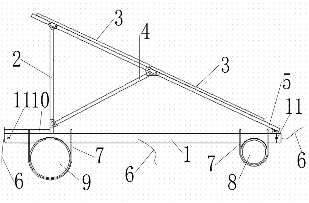
[0015] Attached below figure 1 The present invention will be further described.

[0016] This buoy type water surface photovoltaic power station includes a beam 1, a vertical pole 2 vertically fixed on the beam 1, an inclined oblique pole 5 fixed on the top of the pole 2 and the other end is fixed on the beam 1, and installed on the oblique pole 5 A number of photovoltaic modules 3 are respectively fixed to the front buoy 8 and the rear buoy 9 at the front and rear ends of the bottom of the beam 1 through U-shaped bolts 7, and counterweights are installed inside or outside the front buoy 8 and the rear buoy 9. Since the oblique rod 5 is arranged obliquely, the photovoltaic module 3 is obliquely installed, which can ensure maximum absorption of solar heat. The front buoy 8 and the rear buoy 9 under the beam 1 can float on the water surface, so the photovoltaic power station can be installed on the water surface. The floating form of the photovoltaic power station can avoid the...


PUM


Abstract

The invention relates to a float type water surface photovoltaic power station, which comprises a transverse beam, a vertical rod, an inclined rod, a plurality of photovoltaic assemblies, a front float and a back float, wherein the vertical rod is vertically fixed on the transverse beam, one end of the inclined rod is fixed at the top end of the vertical rod, the other end of the inclined rod is fixed on the transverse beam, the photovoltaic assemblies are arranged on the inclined rod, the front float and the back float are respectively fixed at the front and back ends under the transverse beam through U-shaped bolts, and the interiors or exteriors of the front float and the back float are respectively provided with a balancing weight. The power station has the advantages that as the inclined rod is slantwise arranged, the photovoltaic assemblies are slantwise arranged, and the maximum absorbing of heat of solar energy is ensured; the front float and the back float under the transverse beam can float on the water surface, so the photovoltaic power station is arranged on the water surface, the defect of complicated fixing process of the conventional pile driving method is overcome by the photovoltaic power station adopting the floating method; the construction is simple, the installation is convenient, and the damage to ecologic environments is avoided; by utilizing the balancing weights in the front float and the back float, the wind resistance performance of the photovoltaic power station is realized, and the safety and the reliability are realized.

Description

technical field [0001] The invention relates to the field of solar photovoltaic technology, in particular to a water surface photovoltaic power station. Background technique [0002] With the depletion of traditional energy, the utilization of new energy is changing with each passing day. In particular, the distribution and use of photovoltaic power plants are obviously irrational. The underdeveloped areas in the west have abundant land resources for building photovoltaic power stations, but photovoltaic power generation cannot be fully absorbed locally, and there are difficulties in exporting it; while in the economically developed eastern regions, power resources are in short supply, and a large number of photovoltaic power stations need to be built, but the land resources scarcity. Therefore, in such an uncoordinated situation, the construction of distributed power stations can be given priority to make reasonable adjustments to promote a reasonable balance of electrici...

Claims


Application Information

Patent Timeline
IPC IPC(8): H02S20/30
CPCY02E10/50
Inventor 侯文武李光宗王志雄尹信昀
Owner JINAN GUANGLAN NEW ENERGY TECH
Learn More