Phase control device and method for stable phase transmission of radio frequency signal through optical fiber

A technology of phase-stable transmission and radio frequency signal, which is applied in optical fiber transmission, optical fiber radio, etc., can solve the problems of complex system, low accuracy of optical fiber phase-stable transmission of radio-frequency signal, inability to carry out long-distance phase-stable transmission, etc., to broaden the application field, The effect of speeding up the process of industrialization and reducing requirements

Active Publication Date: 2016-05-18
PLA UNIV OF SCI & TECH
View PDF2 Cites 0 Cited by
  • Summary
  • Abstract
  • Description
  • Claims
  • Application Information

AI Technical Summary

Problems solved by technology

However, due to the asymmetry of the actual round-trip link or the existence of fiber dispersion when the same link uses different wavelengths, the round-trip delay assumption cannot provide accurate delay measurement for the compensation at the sending end. Low precision and complicated system make long-distance stable phase transmission impossible

Method used


Image

  • Phase control device and method for stable phase transmission of radio frequency signal through optical fiber

Examples


Embodiment 1

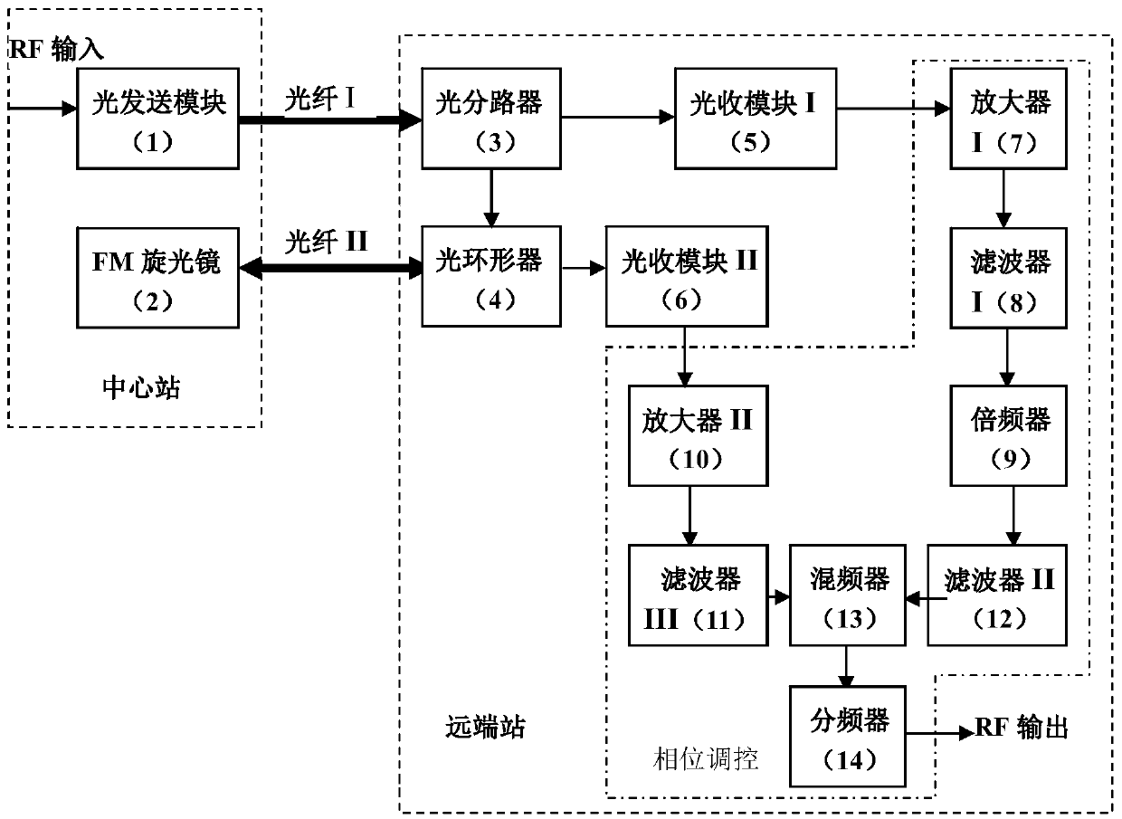
[0019] The phase control device for stable phase transmission of radio frequency signal optical fiber in the present invention is composed of commonly used optical fiber communication devices and electronic components:

[0020] The optical transmission module 1 in the central station uses a broadband high-speed direct modulation DFB laser; the FM optical mirror 2 adopts a Faraday optical mirror;

[0021] In the remote station, the optical splitter 3 adopts a 1×2 optical fiber coupler; the optical circulator 4 adopts a three-port optical fiber circulator; the optical receiving module I5 and the optical receiving module II6 both use PIN+TIA optical receiving components to complete the photoelectric conversion ; Amplifier I7 and amplifier II10 all adopt center frequency to be the electric amplifier of corresponding RF frequency; Filter I8 and filter III11 all adopt center frequency to be the narrow-band electric filter of corresponding RF frequency; frequency; the filter II12 use...


PUM


Abstract

The invention discloses a phase control device and a phase control device for phase-stabilized transmission of a radio-frequency signal. The phase control device comprises a central station and a remote station. The central station comprises an optical transmitting module and an FM (frequency modulation) polariscope. The remote station comprises an optical branching device, an optical receiving module I, an amplifier I, a filter I, a frequency multiplier, a filter II, a mixer, an optical circulator, an optical receiving module II, an amplifier II, a filter III and a frequency divider. The phase control method comprises the following steps of dividing an optical signal sent by the central station and modulated by the radio-frequency signal into two channels in the remote station; returning one of the two channels by the FM polariscope; inputting the two channels into the phase control device together; performing compensation of phase delay and fluctuation, and therefore directly inputting the phase-stabilized radio-frequency signal. According to the phase control device and the phase control device disclosed by the invention, the phase-stabilization precision is not limited by the precision of a measuring system, and precompensation does not need to be performed at a transmitting end. The phase control device and the phase control device are suitable for long-distance transmission and the cascade application of a plurality of remote stations.

Description

technical field [0001] The invention relates to the technical field of radio frequency signal optical fiber transmission, in particular to a phase control device and method for radio frequency signal optical fiber phase stable transmission. Background technique [0002] The demand for stable phase transmission of radio frequency signals in radar systems, deep space detection networks and radio frequency simulation tests is increasing day by day. The traditional coaxial cable transmits radio frequency signals, the transmission attenuation is large, and the phase stability is poor. As the transmission frequency increases, the attenuation increases, and long-distance transmission cannot be carried out. The typical transmission loss of metal cables is about tens of dB / Km, the transmission distance of radio frequency signals in cables is limited, and the thermal expansion coefficient of metal cables is large, such as the typical value of copper is about 0.1-0.2×10 -4 m / °C, causi...

Claims


Application Information

Patent Timeline
Patent Type & Authority Patents(China)
IPC IPC(8): H04B10/2575
Inventor 张宝富李建华周华方涛赵继勇
Owner PLA UNIV OF SCI & TECH
Why Eureka
Try Eureka