Compensator and method for transmission delay in optical fiber time-frequency transmission
What is Al technical title?
Al technical title is built by PatSnap Al team. It summarizes the technical point description of the patent document.
A transmission delay and compensator technology, applied in optical fiber transmission, time-division multiplexing systems, electrical components, etc., can solve problems such as asymmetric two-way delay, inability to synchronize, and greater impact on accuracy, and achieve overcoming delay Asymmetry, the effect of accelerating the process of industrialization and broadening the application field
Active Publication Date: 2016-03-23
PLA UNIV OF SCI & TECH
View PDF5 Cites 0 Cited by
Summary
Abstract
Description
Claims
Application Information
AI Technical Summary
This helps you quickly interpret patents by identifying the three key elements:
Problems solved by technology
Method used
Benefits of technology
Problems solved by technology
The well-connected optical cable network provides a mature physical path for time-frequency signal transmission. The optical network built on the physical network can be used as a reference time synchronization network, but its original design purpose is to serve communication services, so its accuracy Affected by the network greatly, the time synchronization accuracy can only reach the order of hundreds of nanoseconds
But its disadvantage is that the assumption of round-trip and return delays is not easy to meet due to the existence of fiber dispersion when the same link uses different wavelengths, the error of compensation Δθ at the sending end is large, and the two-way time delay is asymmetrical, which makes the transmission accuracy of time-frequency signal optical fiber transmission low, and The output of the photoelectric oscillator at the remote station cannot be synchronized with the central station, and long-distance transmission cannot be realized
Method used
Image
Click on the blue label to locate the original text in one second.
Reading with bidirectional positioning of images and text.
Examples
Embodiment 1
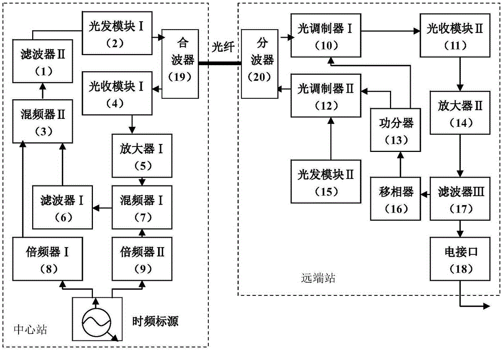
[0023] The compensator for transmission delay in optical fiber time-frequency transmission of the present invention is composed of commonly used optical fiber communication devices and electronic components:
[0024] In the central station, the filter II1 is a narrow-band energized filter corresponding to the center frequency and the time-frequency standard source; the light-emitting module I2 adopts an intensity-modulated DFB light source; the mixer II3 combines the double frequency signal of the time-frequency standard source with the Triple-frequency signal mixing; optical receiving module Ⅰ4 adopts PIN optical receiving components; amplifier Ⅰ5 amplifies the signal output from optical receiving module Ⅰ; filter Ⅰ6 adopts a narrow-band energized filter whose center frequency is three times the frequency of the time-frequency standard source; frequency mixing The frequency multiplier Ⅰ7 mixes the frequency signal corresponding to the time-frequency standard source with the tr...
PUM
Abstract
The invention discloses a compensator and method for transmission time delay in optical fiber time-frequency transmission. The compensator includes a central station and a remote station connected by optical fiber. The central station includes a time-frequency standard source, frequency multiplier Ⅰ, frequency multiplier Ⅱ, filter Ⅰ, mixer Ⅰ, mixer Ⅱ, filter Ⅱ , Optical Transmitter Module I, Multiplexer, Optical Receiver Module I and Amplifier I, the remote station includes demultiplexer, optical modulator I, optical modulator II, optical receiver module II, amplifier II, filter III, phase shifter device, power divider, optical module II and electrical interface. The mechanism of the method is as follows: the central station performs remote injection locking on the photoelectric oscillator of the remote station, and the remote station reversely transmits the error accumulation to the central station, and the central station uses a phase delay and fluctuation control circuit to compensate, so that the photoelectric oscillator of the remote station The output of the oscillator is locked to the central station. The invention eliminates the asymmetry of two-way time delay, makes the transmission accuracy not limited by the measurement accuracy of the system, and can carry out long-distance accurate transmission.
Description
technical field [0001] The invention relates to the technical field of transmission time delay compensation in optical fiber transmission, in particular to a compensator and method for transmission time delay in optical fiber time-frequency transmission. Background technique [0002] Time frequency is the basic physical quantity of matter existence and the basis of people's daily life, production and scientific research. The transmission of time-frequency reference signals includes the foreign GPS / GLONASS multi-source time synchronization-based space-based time-frequency network and the domestic "Beidou" second-generation satellite positioning and navigation system. In general, the space-based time-frequency system can achieve time synchronization accuracy on the order of nanoseconds and 10 -15 Frequency transfer stability per day. However, when the time and frequency of higher-precision clock sources (such as ion clocks, fountain clocks, and optical clocks) need to be tra...
Claims
Application Information
Patent Timeline
Application Date:The date an application was filed.
Publication Date:The date a patent or application was officially published.
First Publication Date:The earliest publication date of a patent with the same application number.
Issue Date:Publication date of the patent grant document.
PCT Entry Date:The Entry date of PCT National Phase.
Estimated Expiry Date:The statutory expiry date of a patent right according to the Patent Law, and it is the longest term of protection that the patent right can achieve without the termination of the patent right due to other reasons(Term extension factor has been taken into account ).
Invalid Date:Actual expiry date is based on effective date or publication date of legal transaction data of invalid patent.