Compact dry toilet installation

A technology for facilities and toilets, applied in the field of compact dry toilet facilities, which can solve the problems of not providing safety and large space

Active Publication Date: 2014-01-08
中渔旅投河北环保科技有限责任公司
View PDF6 Cites 5 Cited by
  • Summary
  • Abstract
  • Description
  • Claims
  • Application Information

AI Technical Summary

Problems solved by technology

The facility requires a large space to meet the requirements of stacking two levels of equipment
Also, the facilities described do not offer absolute safety, especially for young children

Method used


Image

  • Compact dry toilet installation
  • Compact dry toilet installation
  • Compact dry toilet installation

Examples


Embodiment Construction

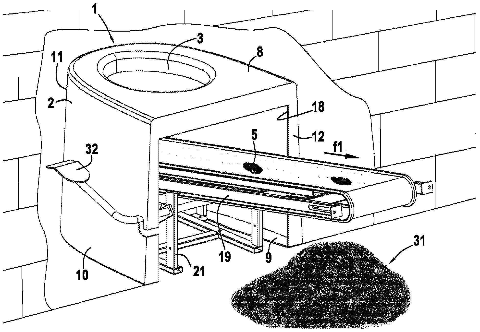
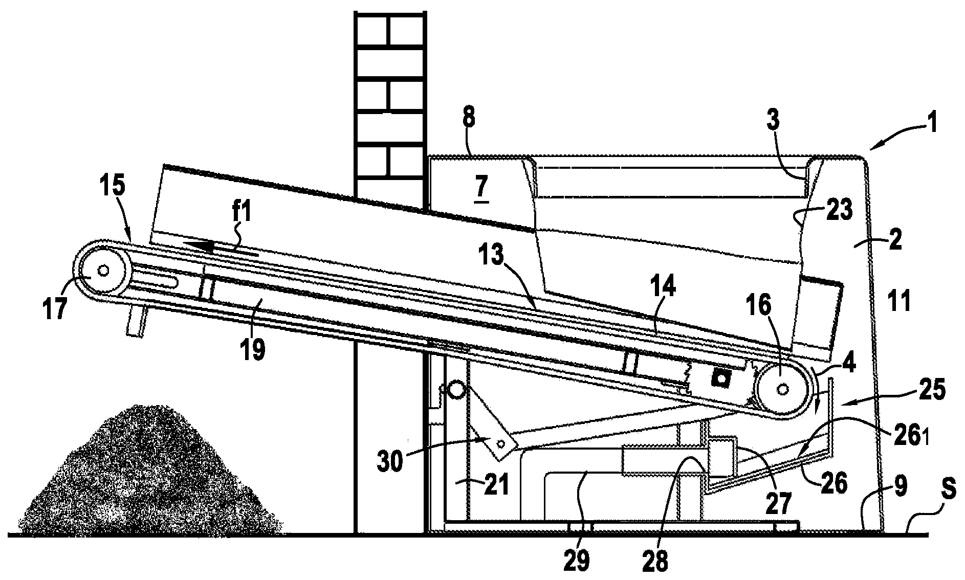
[0038] Such as figure 1 with figure 2 As can be seen more clearly in , the subject matter of the present invention is a compact dry toilet installation 1 comprising a toilet seat 2 defined for the discharge of liquid effluents 4 (such as urine) and solid waste 5 (such as excreta, toilet paper or sanitary napkins)3.

[0039] The toilet seat 2 is in the form of a hollow body defining an internal volume 7 . The seat 2 has an upper surface 8 on which the discharge opening 3 is arranged to extend parallel to a lower surface 9 which rests on the ground S. As shown in FIG.

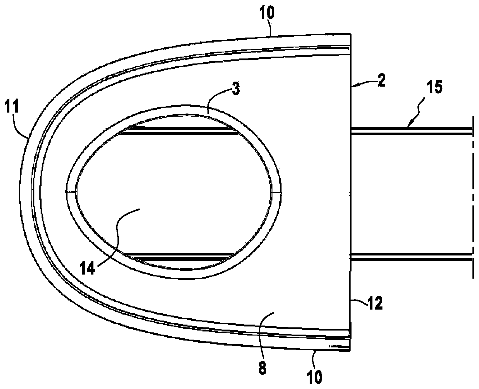
[0040] The upper surface 8 and the lower surface 9 are connected together by side walls 10 , front 11 and rear 12 . exist Figure 1 to Figure 3 In the example shown, the front 11 is a circle, while the Figure 4 In the example shown, the front face 11 is flat. Preferably, the lower bearing surface 9 is defined as a peripheral boundary extending at right angles from the side walls 10 and the front face 11 ....


PUM


Abstract

The invention relates to a toilet installation having: - a toilet seat (2) in the form of a hollow body in which there is formed an opening (3) for removing liquid effluents (4) and solid waste under gravity, - a conveyor belt (15) mounted in an inclined manner, delimiting between a bottom part and a top part a surface (14) for receiving the liquid effluents and solid waste, in order to separate the liquid effluents and the solid waste under gravity, a part of the conveyor belt, starting from the bottom part thereof, being mounted inside the toilet seat, the other part protruding from the rear face of the seat, - a device (25) for recovering the liquid effluents (4) having a reception tank mounted inside the toilet seat.

Description

technical field [0001] The present invention relates to the general technical field of a system for the sanitation, discharge and conversion of human excreta and urine. [0002] The subject of the invention relates in particular to a dry toilet of the kind that ensures the separation of urine and solid waste in order to dispose of them by drying or composting. Background technique [0003] In the prior art, various solutions have been proposed for dry toilet installations, especially by means of composting. For example, patent document FR2442308 describes a device comprising a toilet seat provided with a gravity drain that passes through the floor and opens into a channel for collecting liquid effluent and solid waste such as excrement and toilet paper. s installation. The collection device consists of an endless inclined belt as part of the conveyor belt, which ensures the separation of liquid effluent and solid waste by gravity. This conveyor belt is installed in a cavi...

Claims


Application Information

Patent Timeline
Patent Type & Authority Applications(China)
IPC IPC(8): A47K11/02
CPCA47K11/02Y02A50/30
Inventor 皮埃尔·科隆博
Owner 中渔旅投河北环保科技有限责任公司
Why Eureka
Try Eureka