Pedal travel simulator, actuating unit for a hydraulic brake system and brake system

A technology of pedal travel and braking equipment, applied in the direction of brake transmission device, brake action activation device, brake, etc., can solve the problems of driver's troubles, discomfort, discontinuous pedal feeling, etc., and achieve the effect of low cost

Inactive Publication Date: 2014-01-08
CONTINENTAL TEVES AG & CO OHG
View PDF4 Cites 13 Cited by
  • Summary
  • Abstract
  • Description
  • Claims
  • Application Information

AI Technical Summary

Problems solved by technology

This situation occurs especially when the pedal force is small, that is, within a certain range, the d...

Method used


Image

  • Pedal travel simulator, actuating unit for a hydraulic brake system and brake system
  • Pedal travel simulator, actuating unit for a hydraulic brake system and brake system
  • Pedal travel simulator, actuating unit for a hydraulic brake system and brake system

Examples


Embodiment Construction

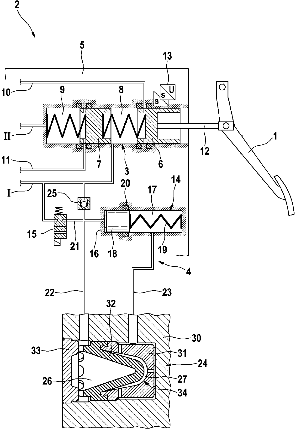
[0033] figure 1 An exemplary operating unit 2 for a hydraulic motor vehicle brake device or a hydraulic booster brake device of the “brake-by-wire” type is shown in a very simplified manner. The operating unit 2 includes a dual-circuit master cylinder or tandem master cylinder 3 that can be manipulated by means of a steering or brake pedal 1 and a pedal stroke simulator 4 that cooperates with the master brake cylinder 3. The master brake cylinder 3 includes two pistons 6 and 7 arranged in a row in a housing 5, the pistons delimiting two hydraulic pressure chambers 8 and 9. In the exemplary brake system of a motor vehicle, the pressure chambers 8, 9 are connected to a pressure medium storage container (not shown) through radial bores formed in the pistons 6, 7 and the corresponding pressure balance lines 10, 11 on the one hand. The connection, wherein it can be shut off by the relative movement of the pistons 8, 9 in the housing 5. On the other hand, the pressure chambers 8, 9 ...


PUM


Abstract

The invention relates to a pedal travel simulator (4, 104) for the hydraulic connection to a pressure chamber (8) of a master brake cylinder (3) of a hydraulic brake system, in particular for motor vehicles, comprising a housing (5, 30, 105) and a simulator piston (18, 118) that is displaceably mounted in the housing, wherein the simulator piston delimits a first hydraulic simulator chamber (16, 116) together with the housing, which simulator chamber can accommodate pressurizing media, wherein an elastic restoring means (19, 119) acts on the simulator piston (18, 118), wherein the pedal travel simulator (4, 104) comprises a second hydraulic simulator chamber (26, 126) for accommodating pressurizing media, said simulator chamber being delimited by an elastically deformable membrane (32, 132). The invention further relates to an actuating unit for a hydraulic motor vehicle brake system of the "brake-by-wire" type and to a hydraulic motor vehicle brake system.

Description

Technical field [0001] The present invention relates to a pedal stroke simulator according to the preamble of claim 1, as well as a control unit for a hydraulic brake system of a motor vehicle and a hydraulic machine having such a pedal stroke simulator EMU braking equipment. Background technique [0002] Hydraulic vehicle braking equipment is known, which is designed as a power-assisted braking equipment and includes, in addition to a manually steerable master brake cylinder, another electronically controllable pressure volume supply device to which the wheel brakes are hydraulically connected The master brake cylinder and the master brake cylinder supplies the pressure and volume used to manipulate the wheel brakes, and the other electronically controllable pressure and volume supply device controls the wheels in the "brake-by-wire" operating mode Brake. Only when the electronically controllable pressure volume supply device fails, the vehicle driver's manpower is used to man...

Claims


Application Information

Patent Timeline
IPC IPC(8): B60T7/04B60T8/40
CPCB60T8/409B60T7/042B60T8/4072B60T7/04B60T8/40B60T11/203B60T13/62
Inventor A·埃克特R·拜尔J·容贝克S·A·德鲁姆J·格拉赫M·贝西尔L·席尔
Owner CONTINENTAL TEVES AG & CO OHG
Why Eureka
Try Eureka