Machining method of cylinder cover air intake slope and cylinder cover clamping device

A clamping device and cylinder head technology, applied in positioning devices, metal processing equipment, metal processing mechanical parts, etc., can solve the problems of high value, restrict the development of processing enterprises, etc., and achieve the effect of reducing processing difficulty

Active Publication Date: 2014-01-15
ANHUI HUALING AUTOMOBILE
View PDF6 Cites 16 Cited by
  • Summary
  • Abstract
  • Description
  • Claims
  • Application Information

AI Technical Summary

Problems solved by technology

[0004] Although this method can complete the processing of the inclined surface of the cylinder head, the development of processing enterprises is greatly limited due to the high value of the equipment.

Method used


Image

  • Machining method of cylinder cover air intake slope and cylinder cover clamping device
  • Machining method of cylinder cover air intake slope and cylinder cover clamping device
  • Machining method of cylinder cover air intake slope and cylinder cover clamping device

Examples


Embodiment Construction

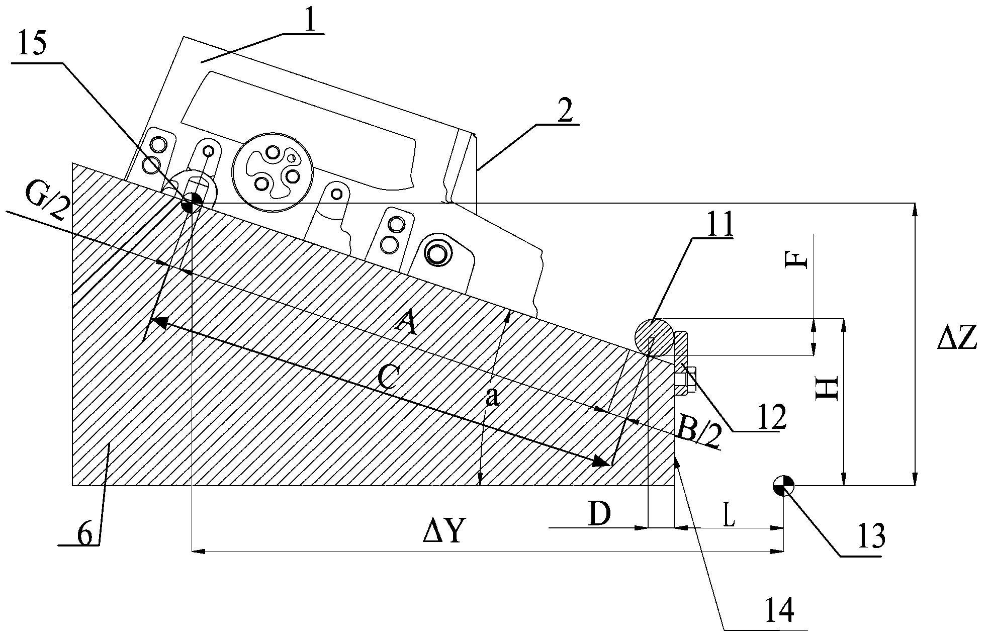
[0030] One of the core purposes of the present invention is to provide a cylinder head clamping device, through which the machining of the intake slope of the cylinder head can be transformed into the machining of the plane, thereby reducing the difficulty of machining, and another aspect of the present invention The purpose is also to provide a method for processing the cylinder head intake slope by using the above-mentioned cylinder head clamping device.

[0031] In order to enable those skilled in the art to better understand the solution of the present invention, the present invention will be further described in detail below in conjunction with the accompanying drawings and embodiments.

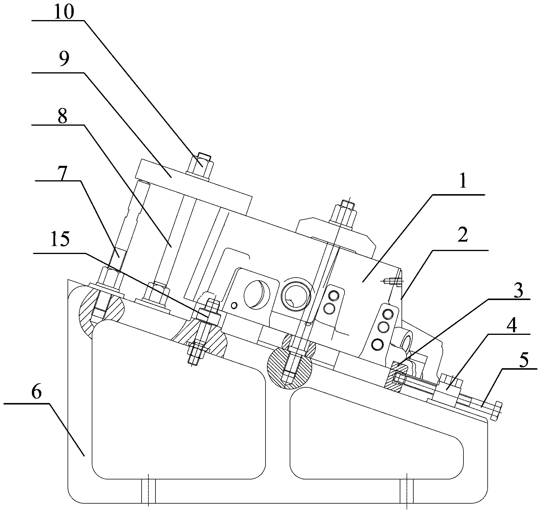
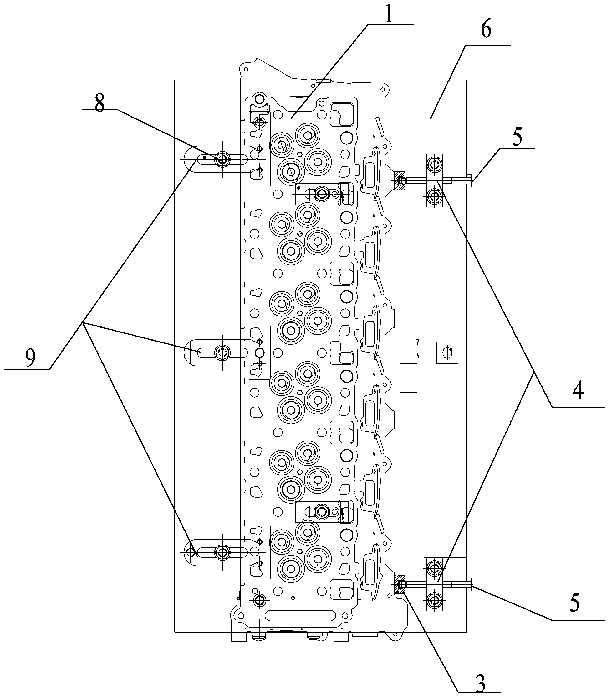
[0032] Please also refer to figure 1 with figure 2 , figure 1 It is an overall schematic diagram of the cylinder head installed on the cylinder head clamping device provided by the embodiment of the present invention, figure 2 for figure 1 top view.

[0033] The cylinder head clam...


PUM


Abstract

The invention discloses a cylinder cover clamping device comprising a slope cushion block and a clamping device body, wherein the section of the slope cushion block is in a right trapezoid shape, the plane where the right-angle waist of the right trapezoid is located serves as the bottom face of the slope cushion block, the plane where the oblique waist is located serves as a cylinder cover clamping face, a cylindrical pin is arranged on the cylinder cover clamping face, the projection, on the cylinder cover clamping face, of the workpiece original point of a cylinder cover falls on the center line of the cylindrical pin, and the included angle between the cylinder cover clamping face and the bottom face of the slope cushion block is the same as the slant angle of a cylinder cover air intake slope. Due to the fact that included angle between the cylinder cover clamping face and the bottom face of the slope cushion block is the same as the slant angle of the cylinder cover air intake slope, after the cylinder cover is installed on the cylinder cover clamping face, the cylinder cover air intake slope is located in the vertical face, and machining for the air intake slope is replaced by machining for the plane located in the vertical face. The invention further discloses a machining method of the cylinder cover air intake slope by the adoption of the cylinder cover clamping device. The machining method can effectively lower production cost for machining the slope.

Description

technical field [0001] The invention relates to the technical field of engine processing, in particular to a method for processing a cylinder head intake slope of an engine block and a cylinder head clamping device used in the processing process. Background technique [0002] As one of the core components of the engine, the cylinder head requires very high machining accuracy, and the intake surface of the cylinder head is a slope. In order to make the overall size of the intake slope and the surface roughness of the intake slope meet the installation requirements, it is necessary to It is very difficult to process the inclined surface because it requires high precision and is an inclined surface. [0003] At present, the commonly used method in the engine production industry is to use expensive five-axis linkage special machine tools and special fixtures to process the intake slope of the cylinder head, and use the rotation and flip of the worktable to process the slope. ...

Claims


Application Information

Patent Timeline
Patent Type & Authority Applications(China)
IPC IPC(8): B23Q3/00B23Q17/22B23P13/02
CPCB23Q3/062B23Q17/003B23Q17/225
Inventor 孙维庆何成琪汪祥支王露刘琳琳王标车欣江益群
Owner ANHUI HUALING AUTOMOBILE
Why Eureka
Try Eureka