
Portable DC electric hoist

A direct current and moving hoist technology, applied in portable lifting devices, hoisting devices, spring mechanisms, etc., can solve the problems of low mechanical efficiency, bulky structure, inconvenient use of lifting equipment outdoors or at home, etc., and achieve safety performance Better, safe and reliable hoisting, avoiding the effect of sudden load drop

Inactive Publication Date: 2014-01-15
贾新天
View PDF8 Cites 3 Cited by
  • Summary
  • Abstract
  • Description
  • Claims
  • Application Information

AI Technical Summary

Problems solved by technology

[0002] With the development of society and the advancement of science and technology, people's economic income has increased significantly, and the material living standard has undergone fundamental changes. People hope that the lifting equipment they buy will be more value for money. Heavy equipment is inconvenient and bulky for outdoor or home use
At present, only a small amount of DC electric hoist products are developed abroad, but the DC electric hoist developed abroad is still a kind of motor and wire rope drum on the same axis, and its disadvantages are large width, heavy structure, mechanical The efficiency is low. Since the DC electric hoist is not equipped with a braking device, there are serious safety hazards. The potential danger is self-evident. At best, the traction machine cannot be used as an electric hoist.
For this reason, many manufacturers and people of insight have developed and trial-manufactured in response to the above-mentioned problems, but so far no relatively ideal products have come out.

Method used


Image

  • Portable DC electric hoist
  • Portable DC electric hoist
  • Portable DC electric hoist

Examples


Embodiment Construction

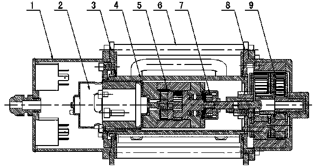
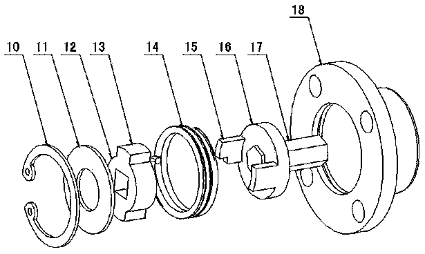
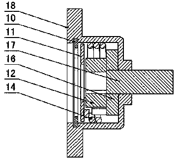
[0014] Figure 1 to Figure 5 As shown, the invention creates a specific embodiment of a portable DC electric hoist, including a controller 1, a DC motor 2, a left end plate 3, a rope drum 4, a first reducer 5, a right end plate 8, and a second reducer 9 , the left and right end plates 3, 8 are fixedly connected as a whole through the connecting rod 6, the rope drum 4 is rotatably arranged on the left and right end plates 3, 8, and the DC motor 2 and the first reducer 5 are fixed and installed on the left end plate 3 and placed in the rope drum 4, the second speed reducer 9 is fixed on the right end plate 8, a transmission brake device 7 is provided between the first speed reducer 5 and the second speed reducer 9, the device includes a Moving jacket 18, brake coil spring 14, input block 12, output block 16, brake jacket 18 is fixed on the first speed reducer 5, input block 12 and output block 16 are arranged in brake jacket 18 and are connected by gasket 11 Positioned with the...


PUM


Abstract

The invention discloses a portable DC electric hoist. The portable DC electric hoist comprises a controller (1), a DC motor (2), a left end-plate and a right end-plate (3 and 8), a rope drum (4) and a first reducer and a second reducer (5 and 9), wherein a transmission braking device (7) is arranged between the first and second reducers (5 and 9) and comprises a braking outer sleeve (18), a braking coil spring (14), an input block (12) and an output block (16); the input block (12) and the output block (16) are arranged in the braking outer sleeve (18); the braking coil spring (14) is sleeved with the input block (12) and the output block (16); a fan-shaped projection (13) is arranged on the input block (12); an arc-shaped stop block (15) is arranged on the output block (16); the fan-shaped projection (13) and the arc-shaped stop block (15) are mutually crossed in a matched manner and a first clamping groove and a second clamping groove (20 and 21) are formed in two sides of the arc-shaped stop block (15); the two ends of the braking coil spring (14) are correspondingly hooked with the first and second clamping grooves (20 and 21). Through the adoption of the structure, the portable DC electric hoist has the advantages of simple and reasonable structure, small size, high transmission efficiency, flexibility and lightness in operation, safety and reliability in use and the like.

Description

technical field [0001] The invention relates to a DC electric hoist, in particular to a portable DC electric hoist that is easy to install and carry, and has good safety performance. Background technique [0002] With the development of society and the advancement of science and technology, people's economic income has increased significantly, and the material living standard has undergone fundamental changes. People hope that the lifting equipment they buy will be more value for money. Heavy equipment is inconvenient and bulky for outdoor or home use. At present, only a small amount of DC electric hoist products are developed abroad, but the DC electric hoist developed abroad is still a kind of motor and wire rope drum on the same axis, and its disadvantages are large width, heavy structure, mechanical The efficiency is low. Since the DC electric hoist is not equipped with a braking device, there are serious safety hazards. The potential danger is self-evident. At best, th...

Claims


Application Information

Patent Timeline
Patent Type & Authority Applications(China)
IPC IPC(8): B66D3/18B66D1/54
Inventor 贾新天
Owner 贾新天
Learn More