Gas pipe for vacuum coating and vacuum coating device applying gas pipe

A vacuum coating and gas pipe technology, which is applied in the field of vacuum coating gas pipes and vacuum coating devices, can solve the problems of color difference of coated products, uniform distribution of difficult gases, time-consuming and other problems, and achieve the effect of ensuring thickness uniformity and color difference uniformity.

Inactive Publication Date: 2014-01-15
SHENZHEN FUTAIHONG PRECISION IND CO LTD
View PDF4 Cites 7 Cited by
  • Summary
  • Abstract
  • Description
  • Claims
  • Application Information

AI Technical Summary

Problems solved by technology

However, after the gas is discharged from the air outlet hole of the gas pipe, it is usually difficult to ensure that the gas is evenly distributed in the coating chamber
In addition, sometimes it is necessary to partially block the air outlet to adjust the distribution of the gas, which is not only time-consuming, but also difficult to ensure the uniform distribution of the gas, and may also cause color difference in the coated product

Method used


Image

  • Gas pipe for vacuum coating and vacuum coating device applying gas pipe
  • Gas pipe for vacuum coating and vacuum coating device applying gas pipe

Examples


Embodiment Construction

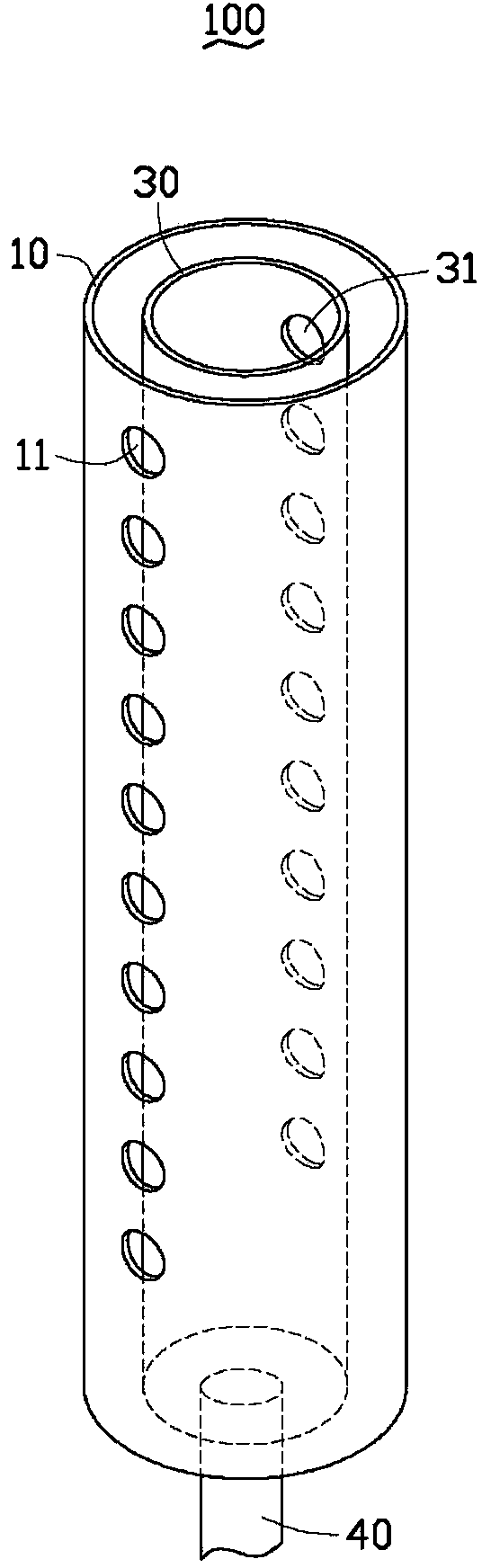
[0013] see figure 1 , the air pipe 100 for vacuum coating in a preferred embodiment of the present invention includes an outer air pipe 10 and an inner air pipe 30 disposed inside the outer air pipe 10 . The inner diameter of the outer air tube 10 is at least twice the inner diameter of the inner air tube 30 .

[0014] The inner air pipe 30 defines a row of first air holes 31 along the axial direction of the pipe wall. The outer air pipe 10 defines a row of second air holes 11 along the axial direction of the pipe wall.

[0015] The preferred relative positions of the second air holes 11 of the row and the first air holes 31 of the row make the distance between the line connecting the center points of the second air holes 11 of the row and the line connecting the center points of the first air holes 31 of the row maximum, That is, the row of second air holes 11 and the row of first air holes 31 are located on the tangent plane along the diameter direction of the outer air tu...


PUM

PropertyMeasurementUnit
diameteraaaaaaaaaa
diameteraaaaaaaaaa

Abstract

A windpipe used in a vacuum coating device includes an outer pipe and an inner pipe positioned in the outer pipe. The inner pipe defines a plurality of first outlets arranged in a line in the peripheral wall of the inner pipe along the axial direction. The outer pipe defines a plurality of second outlets arranged in a line in the peripheral wall of the outer pipe along the axial direction.

Description

technical field [0001] The invention relates to a gas pipe for vacuum coating and a vacuum coating device using the gas tube. Background technique [0002] At present, physical vapor deposition (PVD) is widely used to deposit decorative films on the casings of electronic devices. A gas pipe is provided in the vacuum coating device to deliver working gas and reaction gas to the coating chamber. The existing trachea is a single trachea, and the trachea is evenly opened with a row of stomata from top to bottom. However, after the gas is discharged from the air outlet of the gas pipe, it is usually difficult to ensure that the gas is evenly distributed in the coating chamber. In addition, sometimes it is necessary to partially block the gas outlet to adjust the distribution of the gas, which is not only time-consuming, but also difficult to ensure the uniform distribution of the gas, and may also cause color difference in the coated product. Contents of the invention [000...

Claims


Application Information

Patent Timeline
Patent Type & Authority Applications(China)
IPC IPC(8): C23C14/00C23C14/34
CPCF16L9/18C23C14/228
Inventor 曹达华
Owner SHENZHEN FUTAIHONG PRECISION IND CO LTD
Why Eureka
Try Eureka