Air intake device for furnace tube

A technology of air intake device and furnace tube, which is applied in the direction of gaseous chemical plating, chemically reactive gas, crystal growth, etc., can solve the problems of product 14 pollution in the process chamber, particle problems, and affect product quality and production efficiency, and achieve guaranteed Thickness uniformity, effect of reducing contamination

Active Publication Date: 2018-10-16
SHANGHAI HUALI MICROELECTRONICS CORP
View PDF11 Cites 5 Cited by
  • Summary
  • Abstract
  • Description
  • Claims
  • Application Information

AI Technical Summary

Problems solved by technology

[0005] But, in above-mentioned existing furnace tube, the rotation of magnetic fluid 16 and crystal boat 13, and the relative friction that produces between silicon chip 14 and crystal boat 13 all can bring the problem of particle 15, make process chamber 12 and product 14 polluted
This will seriously affect product quality and production efficiency

Method used


Image

  • Air intake device for furnace tube
  • Air intake device for furnace tube

Examples


Embodiment Construction

[0025] The specific embodiment of the present invention will be further described in detail below in conjunction with the accompanying drawings.

[0026] It should be noted that, in the following specific embodiments, when describing the embodiments of the present invention in detail, in order to clearly show the structure of the present invention for the convenience of description, the structures in the drawings are not drawn according to the general scale, and are drawn Partial magnification, deformation and simplification are included, therefore, it should be avoided to be interpreted as a limitation of the present invention.

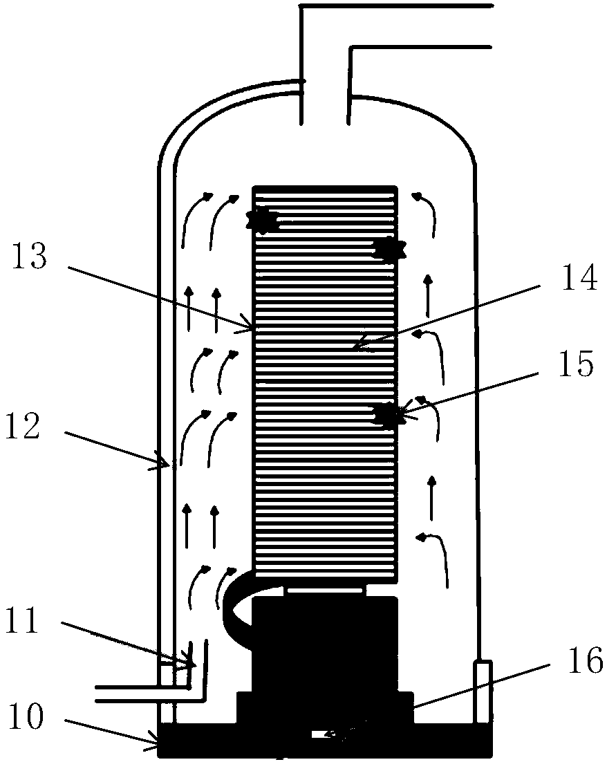
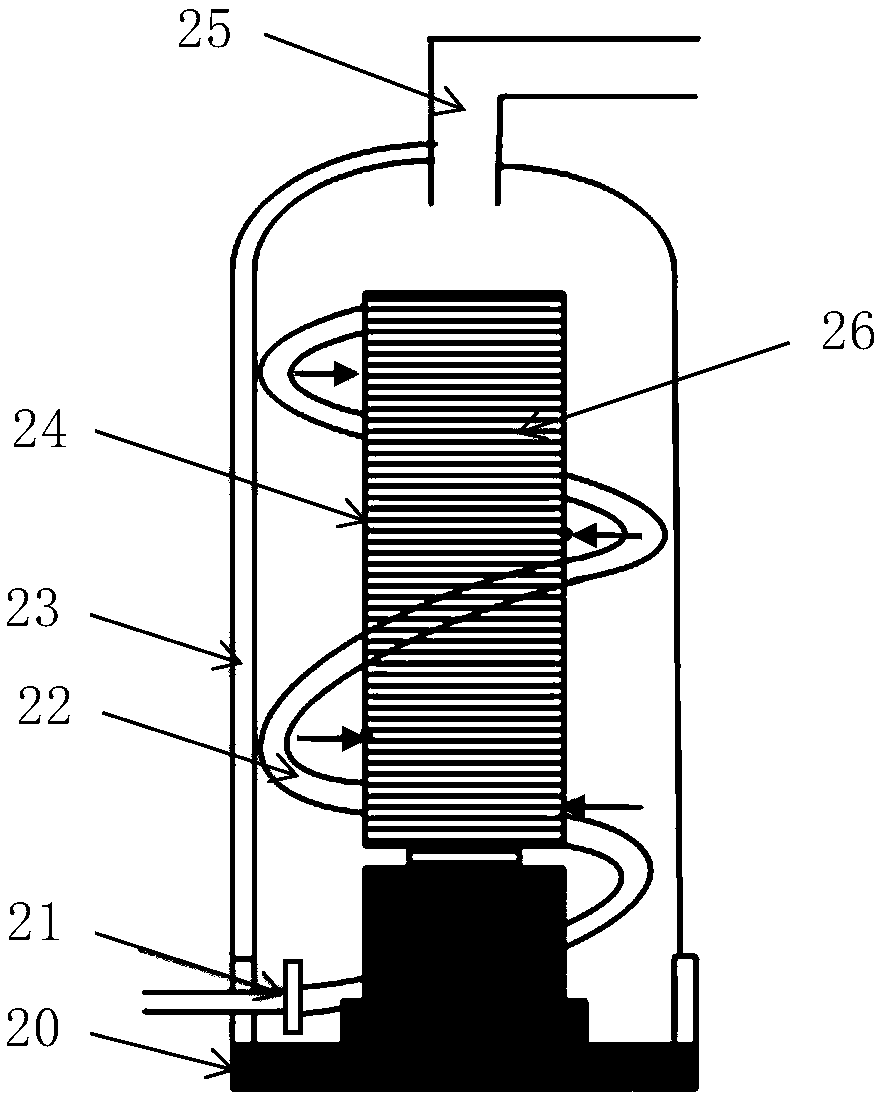
[0027] In the following specific embodiments of the present invention, please refer to figure 2 , figure 2 It is a structural schematic diagram of a gas inlet device of a furnace tube according to a preferred embodiment of the present invention. Such as figure 2 As shown, the air intake device of a furnace tube of the present invention is arran...


PUM


Abstract

The invention discloses an air inlet device of a furnace tube. The air inlet device of the furnace tube comprises an air inlet, an air inlet pipe and a plurality of nozzles, wherein the air inlet is formed in the lower end of a side wall of a process chamber of the furnace tube, and communicated with an external reaction gas pipeline; the air inlet pipe is arranged in the process chamber, one end of the air inlet pipe is connected with the air inlet, the other end of the air inlet pipe is closed, and the air inlet pipe is arranged around a wafer boat in the process chamber from the bottom up; the plurality of nozzles are uniformly arranged in the length direction of the air inlet pipe and face towards the wafer boat; during the process, a reactive gas is introduced into the air inlet pipe through the air inlet, and the nozzles jet the reactive gas to the wafer boat, so that each layer of silicon wafer in the wafer boat is in uniform contact with the reactive gas, and furthermore, the wafer boat is kept in the stationary state to avoid particle pollution caused by rotation of the wafer boat while the thickness uniformity of a product is ensured.

Description

technical field [0001] The invention relates to the technical field of semiconductor processing equipment, and more specifically, to a specially designed furnace tube air intake device. Background technique [0002] With the continuous development of integrated circuits in the direction of high density, more and more components are integrated on a smaller and smaller chip, making the chip less and less tolerant to defects, and more and smaller-sized defects It has gradually become a yield killer. At the same time, the uniformity requirements for the entire silicon wafer are becoming higher and higher. [0003] see figure 1 , figure 1 It is a schematic diagram of an existing furnace tube structure. Such as figure 1 As shown, the furnace tube is provided with a process chamber 12, the bottom of the process chamber 12 is provided with a base 10, and a crystal boat 13 is carried on the base 10, and multi-layer silicon wafers 14 are horizontally installed in the crystal boat...

Claims


Application Information

Patent Timeline
Patent Type & Authority Patents(China)
IPC IPC(8): C23C16/44C23C16/455
CPCC30B25/14
Inventor 祁鹏王智苏俊铭
Owner SHANGHAI HUALI MICROELECTRONICS CORP
Why Eureka
Try Eureka