Tamping device

A technology of clamping and inner pick arms, which is applied in the direction of roads, tracks, ballast layers, etc., can solve the problems of increased line maintenance costs, low reliability of tamping devices, easy damage of internal and external oil cylinders, etc., and achieves simple structure and impact resistance Enhanced capability and high reliability

Active Publication Date: 2015-06-10
CHANGZHOU RUITAI ENG MASCH CO LTD +1
View PDF9 Cites 0 Cited by
  • Summary
  • Abstract
  • Description
  • Claims
  • Application Information

AI Technical Summary

Problems solved by technology

Because the vibrating shaft and the inner and outer pick arms in the existing tamping device are respectively connected through the inner and outer oil cylinders, relying on the inner and outer oil cylinders to transmit the vibration force and clamping force, this makes the impact load directly act on the inner and outer oil cylinders for a long time, causing the inner and outer oil cylinders to easily Damage will affect the service life and increase the maintenance cost of the line; moreover, due to the use of internal and external oil cylinders, the assembly is more complicated and the manufacturing cost is high; multiple (such as 8) internal and external oil cylinders are used to transmit vibration and impact loads at the same time, if a cylinder fails, It will affect the work of the whole tamping device, thus making the whole tamping device less reliable and more energy-consuming

Method used


Image

  • Tamping device
  • Tamping device
  • Tamping device

Examples


Embodiment Construction

[0024] The present invention is described in further detail below in conjunction with the embodiment that accompanying drawing provides.

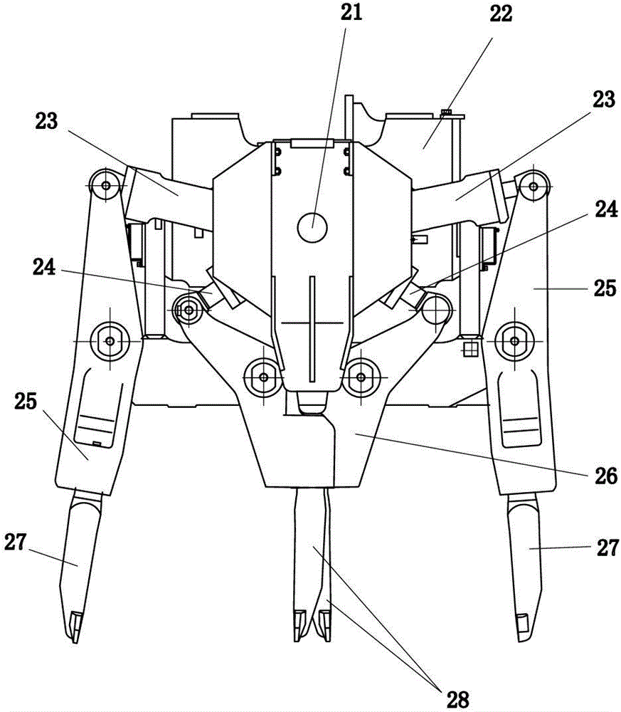
[0025] Such as figure 1 As shown, the uniaxial excitation type tamping device of the prior art includes a vibrating shaft 21, a casing 22, an outer oil cylinder 23, an inner oil cylinder 24, an outer pick arm 25, an inner pick arm 26, an outer tamping pick 27 and an inner tamping Pick 28 etc. The vibration shaft 21 is installed on the casing 22, and the vibration shaft 21 is connected with the inner and outer pick arms 26, 25 through the inner and outer oil cylinders 24, 23 respectively.

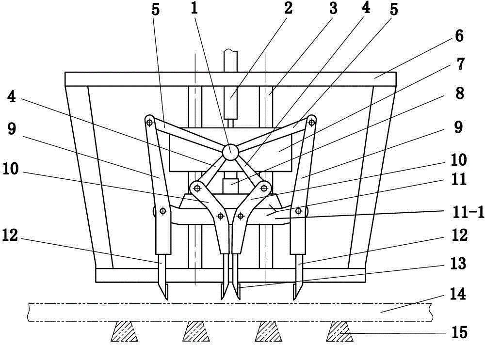
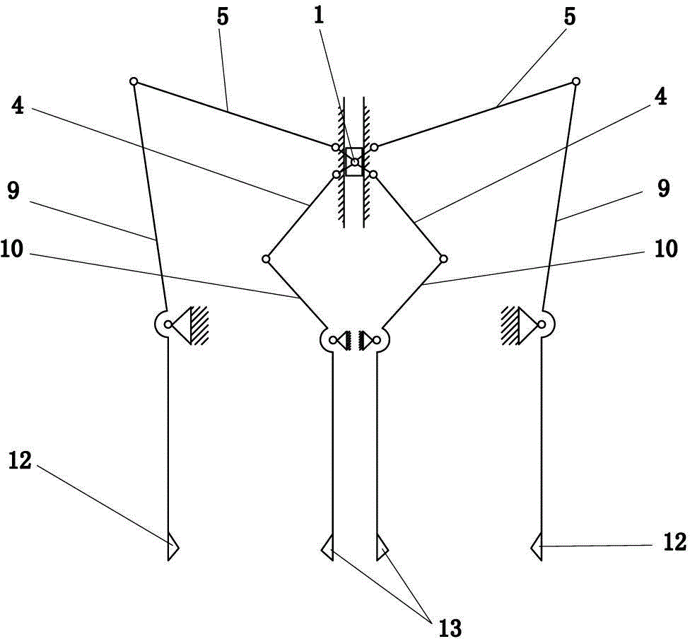
[0026] Such as figure 2 , 3 , 4, 5, and 6, a tamping device of the present invention includes a mobile body 7, an eccentric vibration shaft 1, an inner pick arm 10, and an outer pick arm 9, and the eccentric vibration shaft 1 is rotationally supported on the mobile body 7 On, it also includes the inner pick arm connecting rod 4, the outer pick arm co...


PUM


Abstract

The invention discloses a tamping device of a rail maintaining device. The tamping device comprises a moving body, an eccentric vibration shaft, an inner tamping arm and an outer tamping arm. The eccentric vibration shaft is supported on the moving body in a rotation mode. The tamping device further comprises an inner tamping arm connection rod, an outer tamping arm connection rod, a clamping oil cylinder and a supporting body. One end of the inner tamping arm connection rod and one end of the outer tamping arm connection rod are hinged to the eccentric vibration shaft. The other end of the inner tamping arm connection rod and the other end of the outer tamping arm connection rod are hinged to the upper end of an arm body of the corresponding inner tamping arm and the upper end of an arm body of the corresponding outer tamping arm. The supporting body is located below the moving body. The two ends of the clamping oil cylinder are connected with the moving body and the supporting body respectively. The arm body of the inner tamping arm and the arm body of the outer tamping arm are hinged to the supporting body. The tamping device of the rail maintaining device is high in anti-impact capacity, simple in structure, convenient to assemble and high in working reliability.

Description

technical field [0001] The invention relates to railway maintenance equipment, in particular to a tamping device on a tamping vehicle for tamping railway tracks. Background technique [0002] The tamping device is an important working device in the railway maintenance machinery. It is used to tamp the pillow ballast on both sides of the rail, and cooperates with the track lifting device to eliminate the unevenness of the track and enhance the stability of the track. [0003] Existing tamping devices such as figure 1 Shown, comprise vibration shaft 21, casing 22, outer oil cylinder 23, inner oil cylinder 24, outer pick arm 25, inner pick arm 26, outer pounding pick 27 and inner pounding pick 28 etc. The vibration shaft is installed on the box body, and the vibration shaft is connected with the inner and outer pick arms through the inner and outer oil cylinders respectively. When working, the vibrating shaft provides the exciting force, and the exciting force is transmitted ...

Claims


Application Information

Patent Timeline
Patent Type & Authority Patents(China)
IPC IPC(8): E01B27/20
Inventor 耿路峰王树海翁敏红
Owner CHANGZHOU RUITAI ENG MASCH CO LTD
Why Eureka
Try Eureka