Refrigeration water making device and water making method through collection of water resource in air

A water-making device and air technology, applied in water supply devices, drinking water devices, refrigerators, etc., can solve the problems of not being able to work day and night, not being able to store well, and not being able to produce water well, and to solve the problem of drinking water for humans and animals. Problems, Efficiency Improvement, Effect of Improving Water Production Efficiency

Inactive Publication Date: 2014-01-15
杨志良
View PDF10 Cites 7 Cited by
  • Summary
  • Abstract
  • Description
  • Claims
  • Application Information

AI Technical Summary

Problems solved by technology

The Chinese patent application whose publication number is CN 201599886U discloses an air dehumidification device, and the Chinese patent application whose publication number is CN1740465A records a kind of atmospheric water production device, which all use semiconductor refrigeration technology and can be used in confined spaces (indoor ) for air dehumidification, but it has the following disadvantages that make it unusable for water production from air: the use requirements are high, and it must have a certain humidity (generally greater than 50-60%) to achieve the water production effect. When the humidity is relatively lo

Method used


Image

  • Refrigeration water making device and water making method through collection of water resource in air

Examples


Embodiment 1

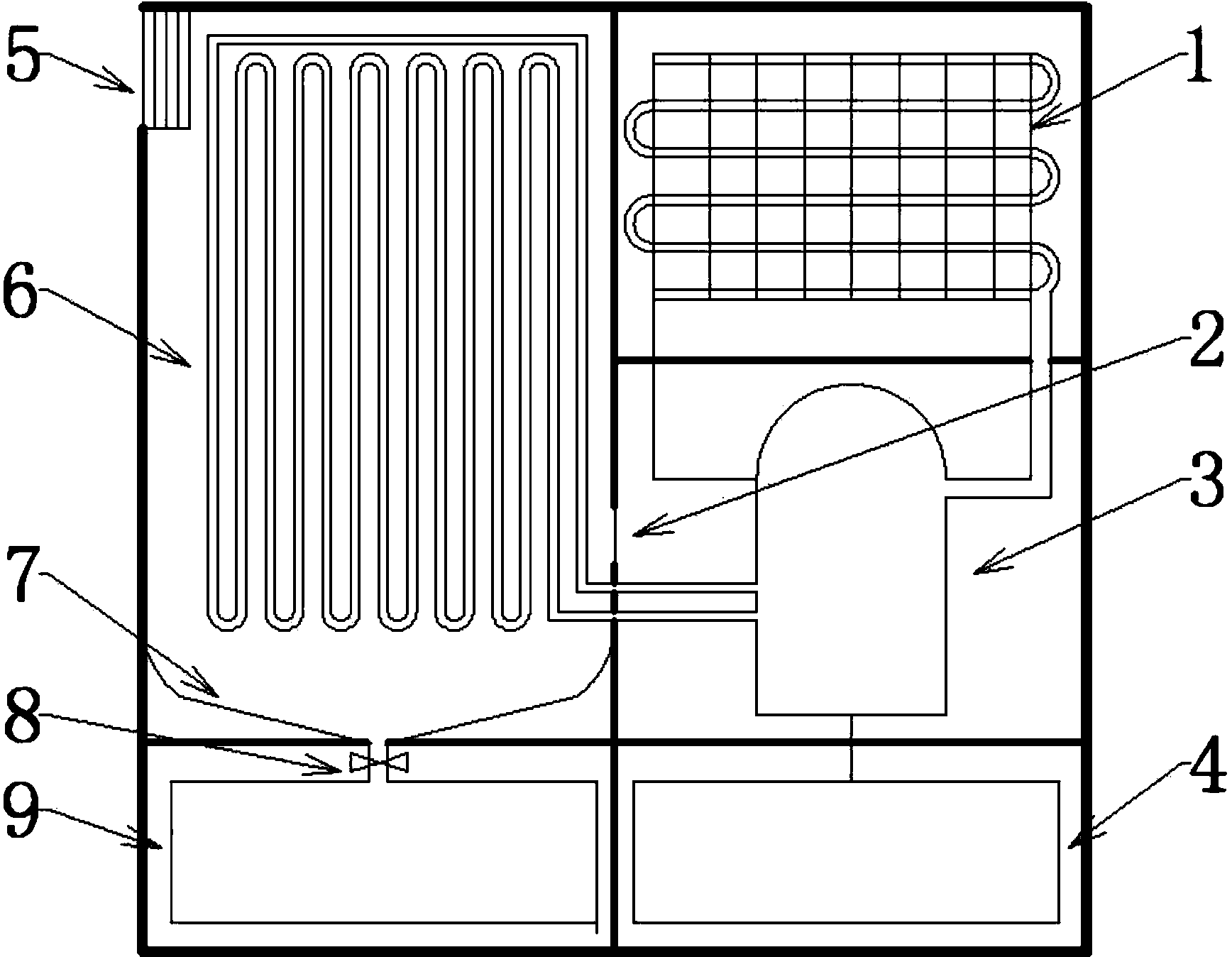
[0039] figure 1 A schematic diagram of the device. The overall device is a box with a volume of 80×30×100cm. The outer layer of the box is wrapped with thermal insulation materials to prevent the water production effect from being affected by changes in the external temperature, and to maintain the low temperature in the box to the greatest possible extent to prevent heat exchange from causing unnecessary waste of energy. The device is divided into left and right parts, the left part is made of thermal insulation material, and the size is 30×30×80cm.

[0040] On the left side of the upper part of the box is a circular air inlet, which is a round hole with a radius of 12.5cm, and a dust cover (not shown in the figure) is installed outside the air inlet. The air inlet is connected to a pipe with the same cross-sectional area as the air inlet (5), and the inner end is opened upward; a fan is arranged inside the air inlet, and the speed is controllable. (6) is a condensing shee...

Embodiment 2

[0053] Different from Example 1, Example 2 is a simplified version of Example 1, and the cost is controlled compared with Example 1. Compared with embodiment 1, embodiment 2 removes the defrosting device, and the water tank (8) forms an angle of 5° with the horizontal plane, and it is an aluminum plate with hydrophobic treatment on the surface, and its corresponding working procedure has also changed.

[0054] When T and t adopt the set fixed values, the water production effect can only be adjusted by adjusting the fan speed. At this time, when the humidity is high, it is necessary to reduce the fan speed to prevent frost accumulation on the condensation sheet (6) If it is too much, the frosting effect will be poor, which will lead to waste of electricity; when the humidity is low, the fan speed needs to be increased to facilitate rapid frost accumulation.

[0055] When T and t are automatically set by the program according to the ambient temperature and humidity, the water pr...


PUM


Abstract

The invention relates to a water making device through collection of the water resource in the air. The device comprises an air inlet pipe, an air outlet pipe, a condensing piece (6), a water collection system (9), a compressor (3) and a refrigerant circulating system (1), wherein the air inlet pipe comprises an air inlet (5) formed in the upper portion of a shell of the device, a fan and an air inlet pipeline, and the fan and the air inlet pipeline are mounted behind the air inlet (5). The air outlet pipe comprises an air outlet (2) and an air outlet pipeline. The water making device is simple and reasonable in structure and convenient to use, an external water source is not needed, vapor in the air can be collected when power is on, and the water making effect is good.

Description

technical field [0001] The invention relates to a device for collecting air and water resources, in particular to mechanical and electronic equipment and a water production method for collecting and developing new water resources through physical processes. Background technique [0002] The distribution of water resources in my country is very uneven, and it is a country short of water. The per capita water volume is only 1 / 4 of the world average, and the average water volume per mu of farmland is only a little more than half of the world average. The climate in Northwest China is dry and rainless, the evaporation is 4 to 11 times that of precipitation, and the total water resources are only 225.4 billion cubic meters. It is one of the most arid and water-scarce regions in the world. There is a huge shortage of water, which directly restricts the development of the local economy and causes environmental degradation. Due to the lack of water, the eight deserts expand wildly a...

Claims


Application Information

Patent Timeline
IPC IPC(8): E03B3/28F25B1/00
Inventor 杨志良
Owner 杨志良
Why Eureka
Try Eureka