A led collimating optical device

A technology of collimating optics and devices, which is applied to semiconductor devices of light-emitting elements, light sources, and parts of lighting devices, etc., can solve the problems of insufficient light output from lenses, LED chip imaging, and easy occurrence of astigmatism, so as to achieve soft and full light spots. Easy to implement, simple and compact effect

Active Publication Date: 2016-04-06
ZHEJIANG JINGRI LIGHTING TECH
View PDF4 Cites 0 Cited by
  • Summary
  • Abstract
  • Description
  • Claims
  • Application Information

AI Technical Summary

Problems solved by technology

[0002] The optical collimation device in the prior art, such as the collimation device involved in a LED light source of the invention patent application with the application publication number CN101713517A, is a glass lens with an aspect ratio greater than 0.1 and is preferably aspheric; however, this kind of lens The light output is not soft enough, and it is prone to astigmatism and glare, and it is easy to produce imaging phenomenon on the LED chip

Method used


Image

  • A led collimating optical device

Examples


Embodiment

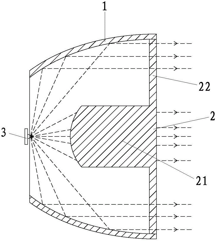
[0013] Example: such as figure 1 As shown, an LED collimating optical device includes a reflective cup 1, which can be made of metal, glass, plastic or other materials, and the inner surface of the reflective cup 1 is coated with a specular reflection layer and a protective layer.

[0014] The reflective cup 1 is provided with a lens 2 whose central axis coincides with the central axis of the reflective cup 1. The lens 2 includes a light guide column 21 and an annular plane lens 22 which is sleeved on one end of the light guide column 21 and integrally connected to the light guide column 21; the annular plane lens The light-emitting surface and the light-receiving surface of 22 have the same light-gathering direction; the light-receiving surface of the light-guiding column 21 is an arc surface; the light-emitting surface of the light-guiding column 21 coincides with the light-emitting surface of the annular plane lens 22; the annular plane lens 22 is fixed on the Ends.

[001...


PUM


Abstract

The invention relates to an optical device, particularly to an LED collimating optical device. The invention is implemented through the following technical scheme: the LED collimating optical device comprises a reflective cup, and a lens which is arranged in the reflective cup and has the axis coinciding with that of the reflective cup; the lens comprises a light guide column and a ring-shaped plane lens sleeved with one end of the light guide column and integrally connected to the light guide column; the light-focusing directions of a light-emitting surface and a light-induced surface of the ring-shaped plane lens are the same. The LED collimating optical device has the advantages of soft and full light spots, no stray light, no chip imaging, no dazzling light and compact and simple structure.

Description

technical field [0001] The invention relates to an optical device, in particular to an LED collimating optical device. Background technique [0002] The optical collimation device in the prior art, such as the collimation device involved in a LED light source of the invention patent application with the application publication number CN101713517A, is a glass lens with an aspect ratio greater than 0.1 and is preferably aspheric; however, this kind of lens The light output is not soft enough, and it is prone to astigmatism and glare, and it is easy to cause imaging of LED chips. Contents of the invention [0003] The purpose of the present invention is to provide an LED collimating optical device, which has a soft and full light spot, no stray light, no chip imaging, no glare, and a compact and simple structure. [0004] The above-mentioned technical purpose of the present invention is achieved by the following technical solutions: an LED collimating optical device, includi...

Claims


Application Information

Patent Timeline
Patent Type & Authority Patents(China)
IPC IPC(8): F21V13/02F21Y115/10
Inventor 程世友
Owner ZHEJIANG JINGRI LIGHTING TECH
Why Eureka
Try Eureka