
Detector for detecting axial displacement degree of coupling

A technology of axial displacement and coupling, which is applied to instruments, measuring devices, mechanical measuring devices, etc., can solve problems such as difficulty in confirming the bearing and total shaft movement coefficient, heavy spare parts, and missed detection and misjudgment of equipment maintenance. , to achieve the effect of eliminating hidden dangers of equipment accidents, easy to carry and easy to carry.

Active Publication Date: 2014-01-15
BAOSHAN IRON & STEEL CO LTD
View PDF4 Cites 1 Cited by
  • Summary
  • Abstract
  • Description
  • Claims
  • Application Information

AI Technical Summary

Problems solved by technology

[0004] In a static state, due to the heavy spare parts, the inspection of the bearing and the main shaft is often distinguished by prying and beating, so it is difficult to confirm the axial "movement" coefficient of the bearing and the main shaft; because the spare parts are too heavy and too It's heavy
Due to the lack of special tools for spot inspection of couplings, equipment maintenance is missed and misjudged

Method used


Image

  • Detector for detecting axial displacement degree of coupling
  • Detector for detecting axial displacement degree of coupling
  • Detector for detecting axial displacement degree of coupling

Examples


Embodiment Construction

[0030] The present invention will be further described below in conjunction with the accompanying drawings and specific embodiments.

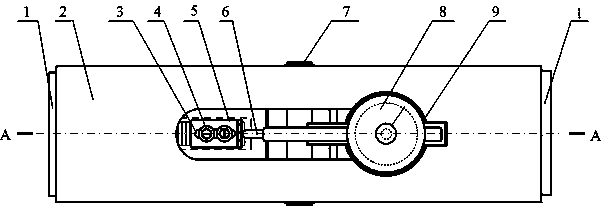
[0031] see Figure 1 to Figure 5 , a coupling axial displacement detector, comprising: a telescopic sliding top block assembly 1, a rotatable square shaft assembly 7, a tension spring 10, a housing, a dial indicator 8, a dial indicator insert 9, and a push rod Block 5;

[0032] A rotatable square shaft assembly 7 is housed between the two telescopic sliding top block assemblies 1, and two extension spring fixing columns 12 are installed on the top of the telescopic sliding top block assembly 1, and two extension springs 10 are mounted on four extension springs. Two telescopic sliding top block assemblies 1 are connected on the fixed column 12 .

[0033] Shell 2,13 is housed on telescopic sliding top block assembly 1 and rotatable square shaft assembly 7 bottom surfaces and both sides, and the middle part of bottom surface shell 2 has long ell...


PUM


Abstract

The invention discloses a detector for detecting axial displacement degree of a coupling. A rotatable square shaft assembly (7) is arranged between two telescoping slide ejector block assemblies (1). The tops of the two telescoping slide ejector block assemblies are provided with two tension springs (10) so that the two telescoping slide ejector block assemblies are connected. The bottom face and the two side faces of the telescoping slide ejector block assemblies and the rotatable square shaft assembly are provided with housings (2, 13). The middle of the bottom housing is provided with a long elliptic opening groove (21). One side of the opening groove is in ellipse shape and is provided with a dial gauge inlay sleeve (9), wherein the inlay sleeve is fixedly arranged on one telescoping slide ejector block assembly and is internally provided with a dial gauge in a close-fitting manner. The other side of the opening groove extends out of an ejector rod stop block (5), wherein the ejector rod stop block is fixedly arranged on the other telescoping slide ejector block assembly. A dial gauge detection ejector rod (6) supports the ejector rod stop block. A spanner clamps a square-edged shaft body shaft core (17) on the rotatable square shaft assembly and thus the telescoping slide ejector block assemblies can be driven to move. The dial gauge is capable of measuring movement amount of the telescoping slide ejector block assemblies.

Description

technical field [0001] The invention relates to a detection device for the axial displacement of a large coupling. Background technique [0002] Large-scale mobile lifting equipment and heavy machinery, such as ship loaders and ship unloaders at port terminals; their power and load connections have special components, namely couplings. The main functions of the coupling are: 1) To achieve a balanced connection between the power source and the load. 2) Realize the centering and balance of the axis operation of the power shaft and the load shaft. 3) Instant buffering effect. The coupling is a coupling device widely used between the motor of the mechanical transmission and the high-speed shaft of the reducer. [0003] Since the coupling acts as a bridge between the power source end and the load end, the degree of wear (hidden danger) of the coupling is related to the operation safety of mechanical equipment and daily production safety. Among them, the wear of bearings is...

Claims


Application Information

Patent Timeline
IPC IPC(8): G01B5/02
Inventor 孔利明孙品生丁海绍
Owner BAOSHAN IRON & STEEL CO LTD
Learn More