Eureka AIR delivers breakthrough ideas for toughest innovation challenges, trusted by R&D personnel around the world.

Switch starting life test circuit and lamp

A technology of life testing and circuit, applied in the direction of lighting testing, etc., can solve the problems of reducing work efficiency, wasting manpower, and high error rate, and achieve the effect of improving accuracy, reducing workload, and improving work efficiency

Inactive Publication Date: 2014-01-15
OCEANKING DONGGUAN LIGHTING TECH +2
View PDF0 Cites 6 Cited by
  • Summary
  • Abstract
  • Description
  • Claims
  • Application Information

AI Technical Summary

Problems solved by technology

[0004] The purpose of the present invention is to provide a circuit for accelerating the life of testing products, which solves the problem of waste of manpower in the existing product testing technology, which not only reduces work efficiency, but also has a high error rate

Method used


Image

  • Switch starting life test circuit and lamp
  • Switch starting life test circuit and lamp
  • Switch starting life test circuit and lamp

Examples


Embodiment 1

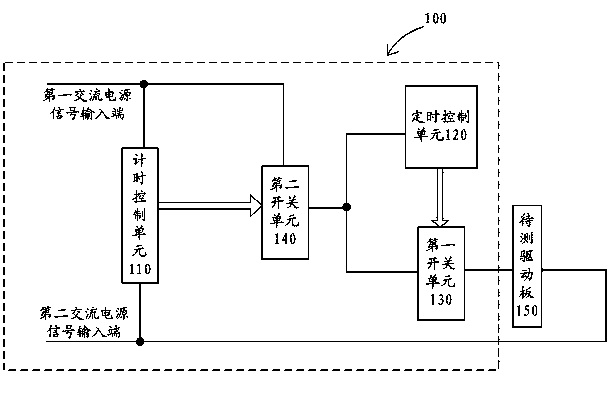
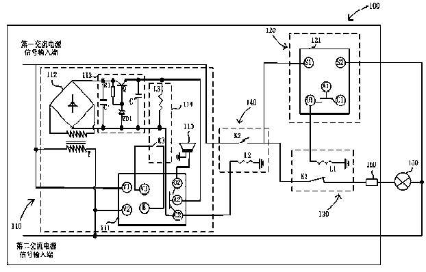
[0032] Such as Figure 1~Figure 2 shown, see figure 1 , the switch starting life test circuit 100 provided by the embodiment of the present invention is used to test the life of the driving board 150 to be tested, including a first AC power signal input terminal, a second AC power signal input terminal, a timing control unit 110, a timing control unit The unit 120 , the first switch unit 130 and the second switch unit 140 .

[0033] The description of the circuit connection relationship of the switch starting life test circuit 100 provided in this embodiment is as follows:

[0034] The timing control unit 110 is used to set the power-on working time of the switch startup life test circuit 100, is connected between the first AC power signal input terminal and the second AC power signal input terminal, and is connected to the second switch unit 140 for use To control the switch state of the second switch unit 140, so as to control the power-on working time of the switch startu...

Embodiment 2

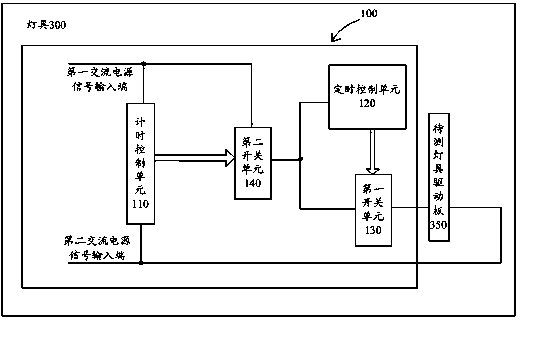
[0056] Such as image 3 As shown, the lamp 300 provided by the embodiment of the present invention includes: a lamp driving board 350 to be tested, and a switch activation life test circuit 100 . Wherein, the switch startup life test circuit 100 includes a first AC power signal input terminal and a second AC power signal input terminal, and also includes a timing control unit 110, a timing control unit 120, and a first switch controlled by the timing control unit 120. unit 130 and the second switch unit 140 controlled by the timing control unit 110 .

[0057] Wherein, the switch connected to the lamp driving board 350 to be tested activates the life testing circuit 100 for testing the life of the lamp driving board 350 to be tested.

[0058] The timing control unit 110 is used to set the power-on working time of the switch startup life test circuit 100, is connected between the first AC power signal input terminal and the second AC power signal input terminal, and is connecte...


PUM


Abstract

The invention belongs to the product detection and test field and provides a switch starting life test circuit which is suitable for a lamp. The switch starting life test circuit comprises a timekeeping control unit, a timing control unit, a first switch unit and a second switch unit. The timekeeping control unit controls the first switch unit so as to control starting or closing of the timing control unit or accelerate electricity work time of a life circuit of a tested product. The timing control unit controls the second switch unit so as to control starting or closing of a driving board to be tested. In the circuit, the timekeeping control unit is used to set and accelerate the electricity work time of the life circuit of the tested product and the timing control unit is used to set conduction time and power-off time of the driving board to be tested so as to achieve a circuit which can automatically control and detect a product life. A manual test is not needed. A manual workload is reduced and test efficiency and accuracy of test data are guaranteed.

Description

technical field [0001] The invention belongs to the field of product detection and testing, in particular to the field of product accelerated life testing. Background technique [0002] In today's society with the development of science and technology, the high stability of products is a common goal pursued by manufacturers, sellers and product users. Taking lighting products as an example, as a new type of energy-saving and environmentally friendly LED light source, there are more and more applications. In this way, not only the life of the LED needs to meet the use requirements, but also the life of the driver board is also very high, so that it can reflect the overall performance of the product. reliability. Therefore, it is also necessary to estimate and predict the life of the driver board circuit inside the lamp product, especially the surge current during the switch startup process has a particularly serious impact on the life of the driver board. [0003] At presen...

Claims


Application Information

Patent Timeline
Patent Type & Authority Applications(China)
IPC IPC(8): G01R31/44
Inventor 周明杰胡波
Owner OCEANKING DONGGUAN LIGHTING TECH
Why Eureka
Eureka Blog
Learn More