A three-dimensional grating and naked-eye 3D display device

A three-dimensional grating and plane display technology, applied in the direction of diffraction grating, optics, optical elements, etc., can solve the problems affecting the visual viewing effect, achieve obvious three-dimensional effect, avoid moiré fringes, and eliminate correlation effects

Active Publication Date: 2016-04-13
TCL CORPORATION
View PDF8 Cites 2 Cited by
  • Summary
  • Abstract
  • Description
  • Claims
  • Application Information

AI Technical Summary

Problems solved by technology

In order to solve the problem of the moiré fringe effect existing in the naked-eye 3D stereoscopic display in the prior art, which affects the visual viewing effect

Method used


Image

  • A three-dimensional grating and naked-eye 3D display device
  • A three-dimensional grating and naked-eye 3D display device
  • A three-dimensional grating and naked-eye 3D display device

Examples


Embodiment 1

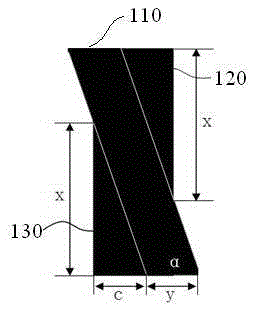
[0035] see image 3 , which is a schematic diagram of the first embodiment of the light-transmitting slit portion of the three-dimensional grating of the present invention. As shown in the figure, the light-transmitting slit portion includes: a first area 110, a second area 120, and a third area 130, wherein the first area 110 corresponds to the sub-pixel structure of a flat-panel display device, and its shape is Parallelogram, including an acute angle in its internal angle; The shape of the second area 120 and the third area 130 are the same, which are all right triangles, and the two obtuse angles in the internal angle of the first area 110 are respectively connected with the second area 120 , the first inner angle of the third area 130 (the angle of the first inner angle is the same as the above-mentioned acute angle); one side of the obtuse angle coincides with the hypotenuse of the second area 120 and the third area 130, and the other side coincides with the hypotenuse of...

Embodiment 2

[0039] Please also refer to Figure 4 with Figure 5 , on the basis of Embodiment 1, it is found through research that when the height of the sub-pixel structure is b and the length of the bottom is a (at this time, the height of the first region of the light-transmitting slit is also b, and the obtuse angle The length of the other side is a). The length of the other right-angled side of the second area and the third area of ​​the light-transmitting slit is half the height of the first area: that is, the length of the other right-angled side of the second area and the third area is b / 2 , which can achieve a better stereoscopic display effect.

Embodiment 3

[0041] On the basis of Embodiment 1, when the degree α of the first internal angle can be arctan (1 / 3), in addition, common arctan (1 / 6), arctan (2 / 9) and other angles can also be used. Here, they are not listed one by one.

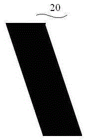
[0042] Compared with the prior art, the above-mentioned three embodiments increase the light-transmitting area of ​​the light-transmitting slit to eliminate the correlation with the sub-pixel structure, thereby effectively avoiding the moiré effect. The schematic diagram of the formed lenticular pattern film is as follows Image 6 shown.


PUM


Abstract

The invention discloses a three-dimensional raster and a naked eye three-dimensional display device. The three-dimensional raster comprises a substrate and a raster graphic film fixed to the substrate, wherein the raster graphic film is provided with light-proof shielding parts and light transmitting slit parts, and the light-proof shielding parts and the light transmitting slit parts are arranged in a repeatedly alternated mode; the light transmitting slit parts are used for eliminating the relevance between the light transmitting slit parts and a sub-pixel structure of a plane display device so as to avoid generation of moire fringes. The light transmitting slit parts can eliminate the relevance between the light transmitting slit parts and the sub-pixel structure of the plane display device by modifying the shape of the light transmitting slit parts on the three-dimensional raster, the generation of the moire fringes is avoided, the naked eye three-dimensional display device has the advantages of being high in brightness, free of moire fringes and obvious in three-dimensional effect and the like, and accordingly comfortable sensation of people to watch three-dimensional display images is improved greatly.

Description

technical field [0001] The invention relates to the technical field of 3D stereoscopic display, in particular to a moiré-free stereoscopic grating and a naked-eye 3D display device. Background technique [0002] In recent years, three-dimensional display technology has developed rapidly and has become a research hotspot. At present, the glasses-type stereoscopic display has been successfully commercialized and entered the households of ordinary consumers. Whether it is polarized glasses or liquid crystal switch glasses, it can separate the two-way images with a certain parallax very well, so that The viewer can see a stereoscopic image with a greater depth of field. However, since people have to wear stereoscopic glasses in the process of viewing such stereoscopic images, people's viewing habits are greatly limited, and there will be discomfort caused by wearing glasses. [0003] The naked-eye stereoscopic display technology does not need to wear any glasses. When people w...

Claims


Application Information

Patent Timeline
Patent Type & Authority Patents(China)
IPC IPC(8): G02B5/18G02B27/22
Inventor 孙贤文谢相伟
Owner TCL CORPORATION
Why Eureka
Try Eureka