Rotary force drive assembly and carbon powder box including same

A driving component and rotational force technology, applied in the field of rotational force driving components and toner cartridges, can solve the problem that the material elasticity of the sphere limiting part is high, affects the power transmission, and cannot be fixed on the power receiving part 105 and the sphere 103, etc. question

Active Publication Date: 2014-01-15
NINESTAR CORP
View PDF6 Cites 20 Cited by
  • Summary
  • Abstract
  • Description
  • Claims
  • Application Information

AI Technical Summary

Problems solved by technology

The universal joint power transmission component adopts split assembly, and the power transmission pin 106 cooperates with the power receiving part 105 and the ball 103 through the shaft hole. When the power transmission component 10 swings along its axis, the power transmission pin also occurs. If there is a gap, the power transmission pin cannot be fixed on the power receiving part 105 and the ball 103, causing the power transmission pin to fall off easily, which will affect the power transmission
Therefore, the disadvantage of this universal joint is that its manufacturing precision is higher, and the manufacturing cost is higher.
If the universal joint does not adopt a split type but is integrally formed, in order to prevent the ball from falling off, the ball stopper 1041 needs to be

Method used


Image

  • Rotary force drive assembly and carbon powder box including same
  • Rotary force drive assembly and carbon powder box including same
  • Rotary force drive assembly and carbon powder box including same

Examples


Embodiment 1

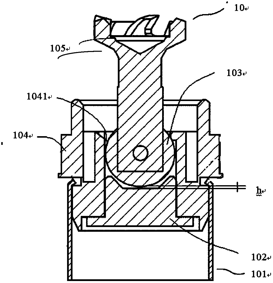
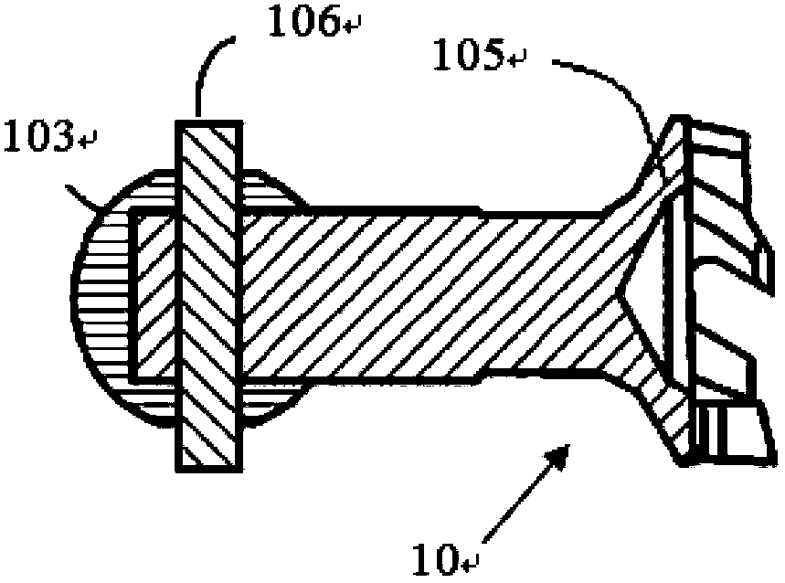
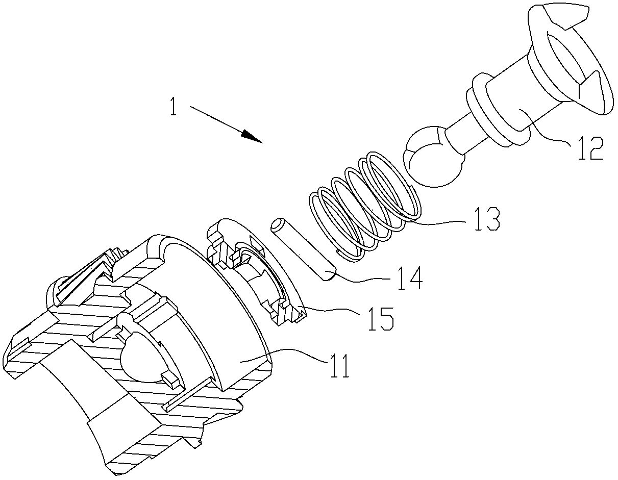
[0075] The exploded view of the technical solution adopted in embodiment one is as image 3 As shown, 1 is the driving force transmission assembly for driving the rotation of the photosensitive element, and the rotation driving force assembly is suitable for any type of photoelectric imaging device and is detachable from the photoelectric imaging device. installed toner cartridge. Wherein, 11 is the photosensitive element gear that is connected to one end of the photosensitive element; 12 is the rotational driving force receiving head that receives the rotational driving force from the electronic imaging device and transmits the driving force to the photosensitive element; Under the circumstances, make the rotating driving force receiving head 12 keep the vertical elastic element, adopt compression spring in the present embodiment, can also adopt the rubber sleeve with elastic force; 14 is the power transmission pin; 15 is the sphere limit baffle. Figure 4 It is a structural...

Embodiment 2

[0086] The exploded view of the technical solution of embodiment two is as Figure 26 As shown, 2 is a driving force transmission assembly, 21 is a photosensitive element gear, 22 is a rotating driving force receiving head, 23 is an elastic element, 24 is a power transmission pin, and 25 is a ball holding block; wherein, the rotating driving force receiving head 22 , the elastic element 23, and the power transmission pin 24 are all consistent with the structures of 12, 13, and 14 of Embodiment 1. The elastic element 23 may be a compression spring or an elastic rubber sleeve, and a compression spring is used in this embodiment.

[0087] The figure is a three-dimensional view of the photosensitive element gear 21, wherein 212 is a pair of sphere limiters, that is, the sphere limiter 152 on the sphere limiter baffle in Embodiment 1, and the sphere limiter in this embodiment The plate and the photosensitive element gear are designed as one. Figure 27 It is the bottom view of th...

Embodiment 3

[0094] The elastic elements in the first and second embodiments above are all cylindrical compression springs, or rubber sleeves with elastic force, and their function is mainly to make the rotating driving force receiving head 12 (22) Keep the vertical state, and absorb the axial movement caused by the gap between the sphere of the rotating driving force receiving head and the sphere holding surface. In the present invention, the shape of the elastic element is configured as a tower, which can also perform the same function. This embodiment is based on the structure of the driving force transmission assembly in Embodiment 1, and the cylindrical compression spring 13 is replaced by Figure 38 As shown in the tower spring 13A, the assembly drawing of its driving force transmission assembly is as follows Figure 39 shown. Meanwhile, the inner diameter of the narrowest end of the tower spring 13A is substantially equal to the outer diameter of the first stepped portion of the r...


PUM


Abstract

The invention relates to a rotary force drive assembly and a carbon powder box including the same. The rotary force drive assembly comprises a photosensitive element gear mounted at one end of a photosensitive element, a rotary driving force receiving head arranged on the photosensitive element gear, and a power transmission pin for transmitting a rotary driving force received by the rotary driving force receiving head to the photosensitive element gear; the end portion of the rotary driving force receiving head is provided with a sphere matched with the power transmission pin, and the sphere is provided with a through groove; the rotary force drive assembly comprises an upper positioning part and a lower positioning part, the power transmission pin passes through the through groove of the sphere, and the power transmission pin and the sphere are relatively fixedly arranged between the upper positioning part and the lower positioning part in the axial direction of the photosensitive element gear. The rotary force drive assembly has a function of arbitrary direction swing at a certain angle, at the same time, the assembly is simple, axial float quantity and radial float quantity of the rotary driving force receiving head can be effectively controlled, and stable and reliable power transmission can be achieved.

Description

technical field [0001] The invention relates to a rotational force driving assembly and a toner cartridge containing the rotational force driving assembly. Background technique [0002] A universal joint driving force transmission assembly is disclosed in the prior art, such as figure 1 shown. The universal joint driving force transmission assembly is connected to one end of the rotating member (that is, the photosensitive element arranged inside the toner cartridge and used to transmit image information), and drives the rotation of the head by receiving the rotational force on the electrophotographic imaging device The driving force is used to drive the photosensitive element to rotate. [0003] Such as figure 1 , 2 As shown, 10 is the universal joint driving force transmission assembly, 101 is the photosensitive element installed on the toner cartridge (not shown), 104 is the gear installed at one end of the photosensitive element, 102 is the ball baffle, 1041 It is t...

Claims


Application Information

Patent Timeline
IPC IPC(8): G03G15/00G03G15/08
Inventor 刘金莲杨妙玲吴连俊戴曙春周永新
Owner NINESTAR CORP
Why Eureka
Try Eureka