Imaging OLED timer

A timer and graphic technology, applied to electronic timers, structural details of electronic timers, instruments, etc., can solve the problems of narrow display viewing angle, few display colors, poor color uniformity, etc., and achieve wide viewing angle, simple structure, colorful effect

Active Publication Date: 2014-01-15
GUAN YEOLIGHT TECH CO LTD
View PDF9 Cites 5 Cited by
  • Summary
  • Abstract
  • Description
  • Claims
  • Application Information

AI Technical Summary

Problems solved by technology

[0007] In order to solve the technical problems of the existing timers with few display colors, poor color uniformity, narrow display viewing angle and large

Method used


Image

  • Imaging OLED timer
  • Imaging OLED timer
  • Imaging OLED timer

Examples


Embodiment Construction

[0052] In order to make the object, technical solution and advantages of the present invention clearer, the implementation manner of the present invention will be further described in detail below in conjunction with the accompanying drawings.

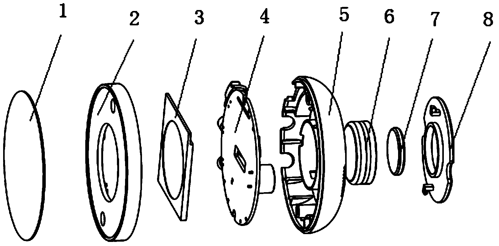
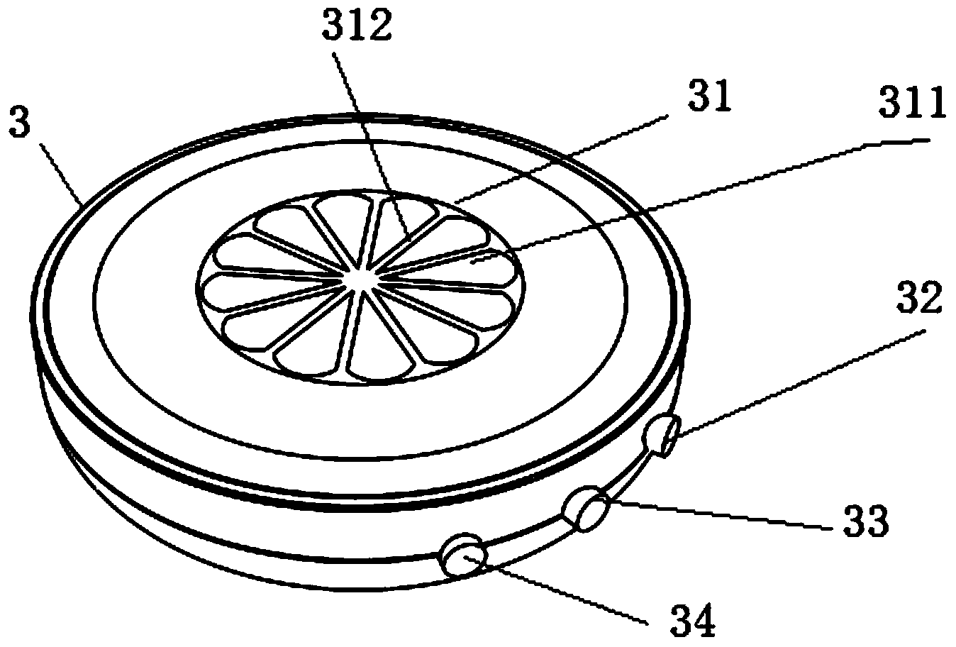
[0053] This embodiment provides a graphic OLED timer, which is simple in structure, light and easy to carry, such as Figure 1-3 As shown, the graphical OLED timer includes a panel 1, an OLED screen body 3, a drive circuit board 4, a housing and a battery 6, the OLED screen body 3 is electrically connected to the drive circuit board 4, and the OLED screen body 3 is formed by multiple Timing display graphics composed of three time indication areas 311, each time indication area 311 is set independently, and is respectively electrically connected with the driving circuit board 4, and the driving circuit board 4 is used to control the graphic display of each time indication area 311. The housing here includes a front panel 2 and a rear co...


PUM


Abstract

The invention discloses an imaging OLED timer which comprises an OLED screen body and a driving circuit board electrically connected with the OLED screen body. A timing display image formed by a plurality of time indicating zones is formed on the OLED screen body. The time indicating zones are independently arranged and are electrically connected with the driving circuit board respectively. The driving circuit board is used for controlling image displaying of the time indicating zones. The imaging OLED timer is simple in structure, light, easy to carry and even in color development, the imaging OLED timer can display any color in the visible light range by adjusting light-emitting color of a light-emitting layer in the OLED screen body, color is abundant, in addition, and the OLED screen body is a self-light-emitting device and is similar to a Lambertian source, so that the imaging OLED timer has the advantages of being wide in body view angle and is not affected by checking angles.

Description

technical field [0001] The present invention relates to the technical field of timers, in particular to a patterned OLED timer. Background technique [0002] A chronograph is a device that uses a specific principle to measure time. Human beings have used timers for thousands of years. From ancient sundials and clepsydra to current clocks and stopwatches, timers have undergone tremendous changes in terms of weight, function, appearance, and scope of application. At present, the existing timers in the market include digital type and mechanical type, and the display patterns and colors are relatively monotonous, and the volume is relatively large. [0003] Patent document CN101390005B discloses a timer with a liquid crystal display device that displays colored segments. The timer includes a cylindrical housing, a display device disposed inside the housing, an electronic control circuit, a battery, and a device for protecting the display. The device displays the protective cry...

Claims


Application Information

Patent Timeline
IPC IPC(8): G04G9/00G04G17/06G09G3/32G09G3/3208
Inventor 倪莹莹吴海燕王静王崟张祝新胡永岚
Owner GUAN YEOLIGHT TECH CO LTD
Why Eureka
Try Eureka