

High-performance cache system and method
A memory and instruction memory technology, applied in the computer field, can solve various problems such as cache misses, and achieve the effects of avoiding capacity misses, reducing power consumption, and speeding up
- Summary
- Abstract
- Description
- Claims
- Application Information
AI Technical Summary
Problems solved by technology
Method used
Image

Examples
Embodiment 800
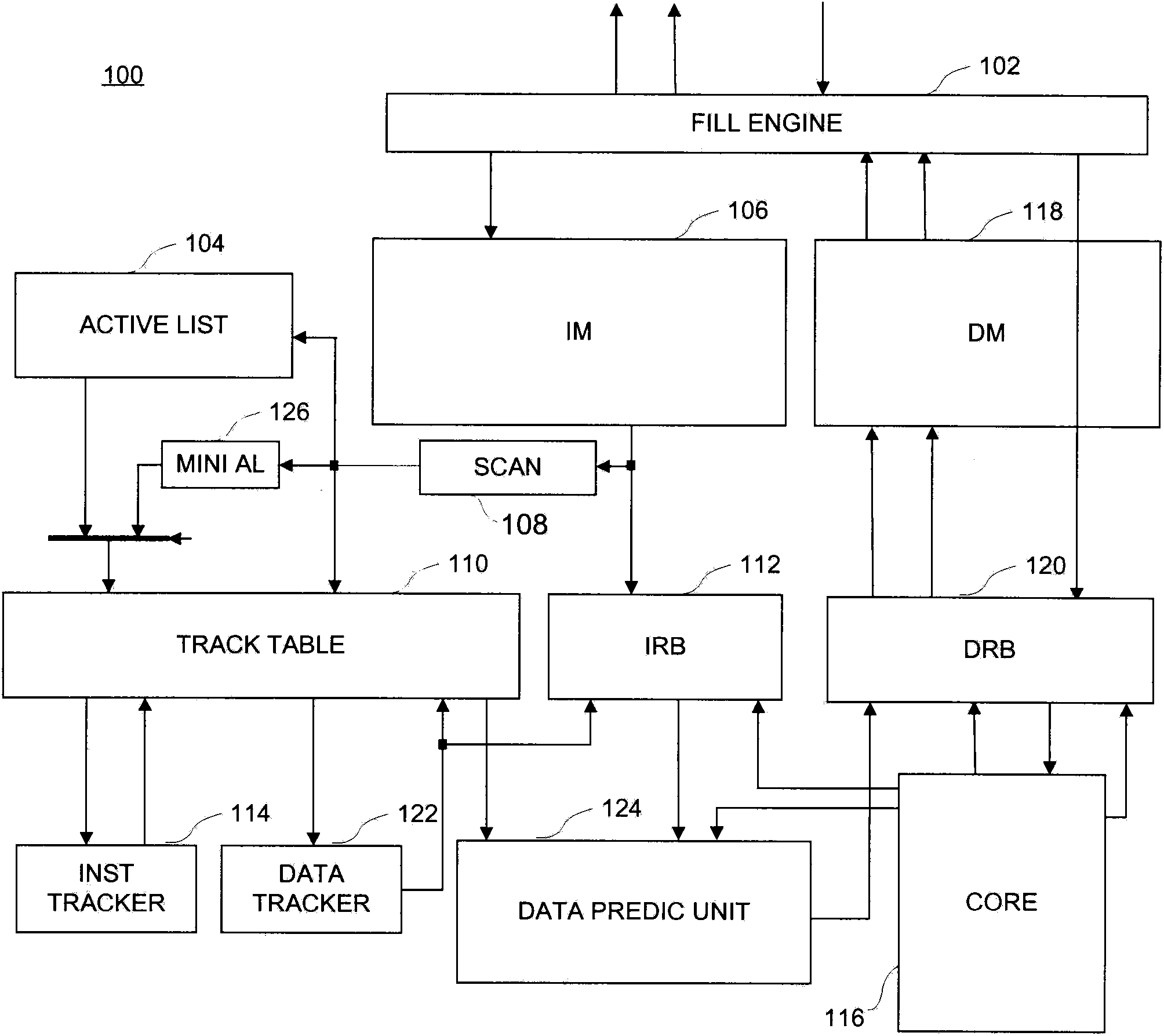
[0167] In this embodiment, the instruction read buffer 112 is composed of a register set 802, which has the same capacity as an instruction block and contains the current instruction block being executed by the processor. For ease of description, it is assumed that an instruction block has only two instructions, that is, the register bank 802 only includes registers capable of storing two instructions. The case for including more directives is similar.
[0168] In this embodiment, the current instruction block including the instructions to be executed by the processor core 116 will be stored in the register set 802 . Once the instruction to be executed by the processor core is not in the current instruction block, the instruction block where the instruction is located is read from the instruction memory 106 according to the first address pointer 614 of the instruction tracker 114 and stored in the register set 802, and at the same time The instruction information extracted by...
Embodiment 1300
[0223] In this embodiment, the data predictor 1216 includes an extractor 1334, a base address register value change step filter 1332 and an adder 1204. Extractor 1334 includes decoder 1322 and extractors 1324 , 1326 , 1328 . The extractor 1334 examines the instruction 1302 being acquired by the processor core 116, decodes it by the decoder 1322 to obtain the instruction type 1310, and then extracts the target register number 1304 in the register update instruction from the instruction 1302 according to the decoding result, The change amount of the register value 1306 and the base address register number 1308 of the data access instruction. Usually, register numbers, register value changes, etc. in different types of instructions can be located in different positions in the instruction word, so these information can be extracted from the corresponding positions in the instruction word according to the decoding result of the instruction type. In addition, the base address regis...
Embodiment 2040
[0316]In this embodiment, the registers and comparators in the address information matching unit are divided into three matching modules 2052, 2054 and 2056, and each matching module includes at least one register and a corresponding comparator. The address information configuration module 2042 includes a start address memory 2044 , an end address memory 2048 , a decider 2050 , an auto-incrementer 2046 and a selector 2058 . The entries in the start address storage 2044 and the end address storage 2048 correspond one to one, that is, one start address entry corresponds to one end address entry. Such as Figure 20A According to the embodiment, each register in the address information matching unit has an address, and the address can be obtained by mapping a row number or an index address. To determine which of these registers are used to store the instruction row address as an example, assume that there are several registers used to store the row address in the matching modules...
PUM
 Abstract
Description
Claims
Application Information