Wire tensioning mechanism

A wire and wire rod technology, which is applied in the field of wire production stranding equipment, can solve the problems of complex adjustment process, unfavorable production efficiency of stranding machine, complicated device structure, etc., and achieves simple tension force, is conducive to normal operation, and satisfies the production process. desired effect

Inactive Publication Date: 2014-01-15
ZHONGJIANG KAIXUN ELECTRONICS
View PDF6 Cites 0 Cited by
  • Summary
  • Abstract
  • Description
  • Claims
  • Application Information

AI Technical Summary

Problems solved by technology

[0004] Aiming at the problem that the structure of the device for tensioning the wires on the existing wire stranding machine is not only complicated, but also the adjustment process is complicated when applied to wires with different wire diameters, which is not conducive to the production efficiency of the wire stranding machine, the present invention provides a wire tensioning mechanism

Method used


Image

  • Wire tensioning mechanism
  • Wire tensioning mechanism

Examples


Embodiment 1

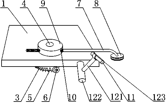
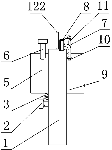
[0030] Such as figure 1 with figure 2 As shown, the wire tensioning mechanism includes a wire tensioning mechanism and a disconnection alarm mechanism. The wire tensioning mechanism includes a flat plate-shaped seat plate 1, a rotating shaft 4, a spring 3, a first disc 5, and a second disc 9 and the twisting rod 7, the seat plate 1 is provided with a circular through hole, and the rotating shaft 4 forms a clearance fit with the circular through hole, and the first disc 5 and the second disc 9 are respectively fixedly connected to the rotating shaft 4 and the first disk 5 and the second disk 9 are respectively located on both sides of the seat plate 1, one end of the spring 3 is fixedly connected to the side of the first disk 5, and the other end of the spring 3 is fixedly connected On the seat plate 1, the second disc 9 is also provided with an internally threaded hole parallel to the plane of the seat plate 1 in the axial direction, and one end of the twisted wire rod 7 is ...

Embodiment 2

[0033] The sensor fixing device includes a fixed rod 122, a connecting rod 121 and a hoop clamp 123, the fixed rod 122 is fixedly connected to the upper end of the seat plate 1, one end of the connecting rod 121 is fixedly connected to the fixed rod 122, and the other end of the connecting rod 121 The hoop clip 123 is connected, and the hoop clip 123 is in the shape of a hoop, and the acceleration sensor 11 is located in the hoop body of the hoop clip 123 .

[0034] Specifically, in this embodiment, the set hoop-shaped clip 123 is made of a steel sheet made of 55Si2Mn into a hoop shape by bending, one side of the hoop-shaped clip 123 is provided with an opening, and the hoop-shaped clip 123 on both sides of the opening is The hoop body is formed between them, the acceleration sensor 11 adopts a piezoelectric acceleration sensor, the acceleration sensor 11 is placed in the hoop body, the outer wall of the acceleration sensor 11 is in contact with the inner wall of the hoop clip ...

Embodiment 3

[0036] The present embodiment is further limited on the basis of embodiment 1, as figure 1 with figure 2 As shown, it also includes a first spring bolt 2, the seat plate 1 is provided with a first internally threaded hole, the first spring bolt 2 is threadedly fitted with the first internally threaded hole, and the number of the first internally threaded hole More than one, the first internally threaded holes are arranged on the seat plate 1 below the first disk 5, and the first internally threaded holes are distributed in the same vertical direction, the fixed connection point between the spring 3 and the seat plate 1 is at the One spring bolt 2 on.

[0037] Also includes a second spring bolt 6, the side of the first disc 5 is provided with a second internally threaded hole, the second spring bolt 6 is threadedly fitted with the second internally threaded hole, and the second internally threaded hole The number is 8, which are evenly distributed on the side of the first di...


PUM


Abstract

The invention discloses a wire tensioning mechanism which comprises a wire tensioning mechanism and a broken wire warning mechanism. The wire tensioning mechanism comprises a base plate in a flat plate shape, a rotating shaft, a spring, a first disc, a second disc and a strand rod. A round through hole is formed in the base plate. The broken wire warning mechanism comprises an acceleration sensor, a sensor fixing device and a warning device. The acceleration sensor is arranged on the sensor fixing device, the acceleration sensor is connected with the warning device through an electric cable, and the acceleration sensor is located in a skimming area of the strand rod with the rotating shaft as the rotating center. The wire tensioning mechanism is simple in structure and convenient to operate. When the wire diameter and tension force of the wire need adjusting, the wire tensioning mechanism can meet the process requirement through simple adjustment. The wire tensioning mechanism further can be favorable for reducing the possibility of wire breaking or loosening in the tensioning process of the wire, and the wire is broken, the automatic warning function is achieved.

Description

technical field [0001] The invention relates to the field of conductor production stranding equipment, in particular to a conductor tensioning mechanism. Background technique [0002] In the production process of the wire, whether it is before the coil winding of the single-strand wire or the twisting of the multi-strand flexible wire, in order to obtain a smooth transition single-strand wire or a tight coil wound in a loop, it is necessary before the wire is twisted. A certain force is exerted on the wire, so that the wire before entering the stranding process is tensioned under the force, so that the wire tends to be straight. [0003] The device used for tensioning the wires on the existing stranding machine generally uses multiple sets of rollers, the wires pass between each set of rollers, and each set of rollers applies compressive stress to the wires, and the wires are tensioned between two adjacent sets of rollers straighten. However, this structure is not only com...

Claims


Application Information

Patent Timeline
IPC IPC(8): H01B13/02
Inventor 黄建国黄建云黄旭
Owner ZHONGJIANG KAIXUN ELECTRONICS
Why Eureka
Try Eureka