Control circuit and synchronous rectification control circuit
A control circuit, synchronous rectification technology, used in control/regulation systems, high-efficiency power electronic conversion, electrical components, etc.
- Summary
- Abstract
- Description
- Claims
- Application Information
AI Technical Summary
Problems solved by technology
Method used
Image


Examples
Embodiment Construction
[0047] In order to make the above objects, features and advantages of the present invention more comprehensible, a preferred embodiment will be described in detail below together with the accompanying drawings.
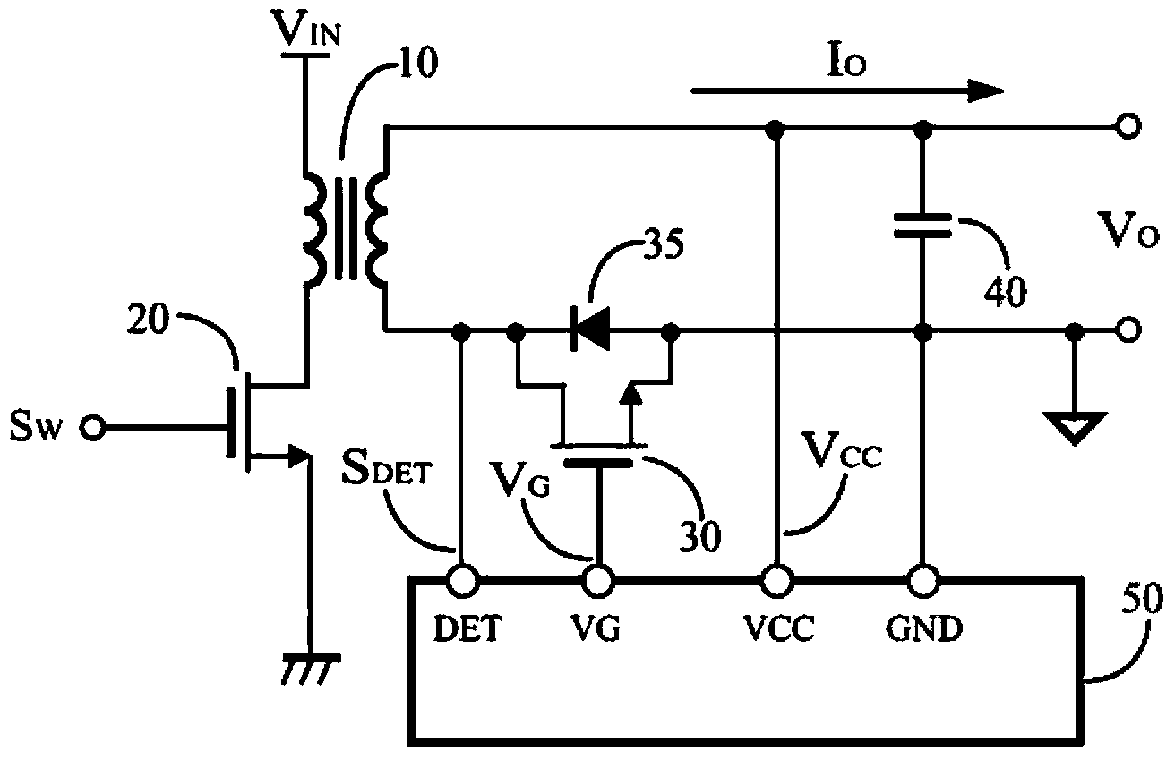
[0048] image 3 shows a power converter according to an embodiment of the present invention. By switching signal S W The controlled transistor 20 is coupled to switch the transformer 10 to convert from the input voltage V IN The energy is transferred to the output voltage of the power converter V O . When rectifier 35 (or the body diode of transistor 30) is turned on to transfer power from transformer 10 to output capacitor 40, transistor 30 will turn on to reduce rectifier 35 conduction losses (rectifier 35 forward bias voltage drop). The operation of transistor 30 makes it behave like a synchronous rectifier. The terminal DET of the synchronous rectification control circuit 50 is coupled to the transistor 30 and / or the transformer 10 to detect the signal S DET...
PUM
 Abstract
Description
Claims
Application Information